
2 September 2026
This transcript was generated automatically and may contain errors.
Afternoon, everyone. Good afternoon, everyone. Welcome to this Cemtech Seminar webinar. It is 2:00 PM here in Dublin, later afternoon across Africa Evening in the Middle East, India and Southeast Asia. Still morning in North and South America. Welcome to everybody across the world. Oh dear. My slides aren't moving. Anyhow, I'll go on. My name is Jim O'Brien. I'm very honored to deputize for Tom Armstrong in chairing this webinar today. Tom is at the Cemtech Conference in Jakarta. I only hope I can share this session as professionally as he always does. Sorry, I can't move the slides here for some reason and then switch off. I can share, I'll share a similar set. Do you wanna reshare that?
Yeah, please, Tom. Yeah. Sorry for this slight delay, if Tom can bring up those slides. Thanks, Tom. Brilliant. Yeah. my name is Jim O'Brien. I'm very honored to deputize for Tom Armstrong in this, chairing this webinar today, as Tom is in our Cemtech Asia Conference in Jakarta, this webinar. yeah. this webinar is the sixth in the 2024 series of webinars, those to date, having covered hot topics including carbon capture, grinding, alternative fuels, digitization, and energy efficiency. So all of these are keeping you in touch with the very latest technology. This webinar is series is hosted by the International Cement Review, the Premier Cement Industry magazine Each month.
It covers in amazing breadth and depth industry, news, technology developments, company and market trends, energy efficiency, and I really look forward each month to receiving my copy of the International Cement Review. One advantage of subscribing to the International Cement Review is receiving a free copy of the Cement Plant Operations Handbook, a real treasure of must know process and engineering technology. Alternatively, you can get a free copy of the Cement Plant Environmental Handbook. A must have reference book on all aspects of sustainability performance. Again, essential reading for industry practitioners who wish to excel.
For those who really want to know what's happening in the cement industry around the world. The Global Cement Report provides a compendium of industry information for over 170 countries in itself. A most useful reference book on world geography, economic trends and cement plant developments. Emec also runs three in-person key conferences each year that for the middle East and North Africa took place in Dubai in February. Cemtech Asia has just concluded in Jakarta, Indonesia, and was, by all accounts a hugely successful event in both terms of attendance and technical content.
Emec Europe will take place this year in Warsaw from September 29 to October the second, which will be the key event for meeting people from the industry across Europe. While webinars are great, there is nothing like meeting people in person at these in-person meetings. Now let's focus on today's SE webinar, which focuses on the absolutely essential part of the process. In other words, the pyro processing, where the latest technology and next generation advances can truly optimize the kiln process, thermal efficiency, and optimize decarbonization.
We have in this session today four excellent presentations which really expose the very latest technology in pyro processing to run through them in reverse order. The fourth is cement plant processing thermo thermography by Hassan Choan of HDH infrared systems of France. Then ine Clay, how to get started by Joel Maya, FCT Combustion. the second is CO2 reduction Adaptation and Resilience by Tahir Abbas of Nar Nar Limited. And the first for which with we'll start in a moment, is satellite success by Nicola Vic of UN Scon.
And before we start, just to tell all our participants all over the world that this session is being recorded, and the recording plus the presentations will be circulated to everybody afterwards, within a day or two to everybody who has signed up for this webinar. So, I'll unshare my screen at this stage and welcome Nicola Vic, Nicola, just to introduce him, and you can start sharing your screen. Nicola began his career in the cement industry as a shift supervisor with cmex.
He went to John, join other cement multinationals, where he held the roles of chief process and commissioning engineer respectively before leaving to take up the position of senior mechanical process engineer at Astro Plan Consulting. Currently, Nicola is sales manager at Uni uniforms simcom, which specializes in high efficiency hill and Cal signer burners, and he manages Unim sales team all over the world. his presentation will be Burner satellite success. And Nicola, we're delighted to hand over to you. The virtual floor is yours. Thank you, Jim. can you just confirm that everything is okay that that I share my screen? Yes. Perfect. Yeah. Can see you and hear you. Excellent.
good afternoon, everyone. first, I, I would like to thank you for giving us opportunity to present our company and, and our findings. We are excited to share result of our research, which, which has been going for for several decades. I have to say that most of our research, especially in product development, is conducted in collaboration with our clients. And as we work together to effectively respond to all market and process demands I will share some specifics of our work about the kiln burner and satellite burner, and how we can assist clients in burning secondary fuels more efficiently, efficiently.
At the end of the presentation, I will also share some case studies to illustrate our results. first I want to briefly discuss the types of secondary fuels, where and how they can be fired, and what considerations are necessary when, when using secondary fuels. Next, we will briefly cover firing through the main burner. Then we will move to our main topic satellite burner, which has become increasingly important in recent years, and I will conclude the presentation with case studies that illustrate the use of both the main burner and satellite burner. I would like just briefly to introduce UN for those who may not be familiar with our company.
Uni term was founded in 1945 in Vienna, initially focusing on producing oil boilers and household heating systems. Over time, we expanded into other industries, and in 1953, we installed our first kil burner. Originally we used two channel and three channel burners until finally, we, we patented MIS technology in 1992, MIS stands for Mono Duct System, which was a innovative solution to bring complete primary air flow into a mechanically adjustable server with a minimum loss of momentum. In 1997, there was a change in ownership, and Mr. Leder acquired the company.
Under his leadership company strategy shifted to primarily focus on cement and mineral market, particularly applications involving rotary kills. Since then we have relocated to a new office building and continued to concentrate exclusively on these two industries. we have installed over 600 firing systems in 92 countries up to date. And all of our burners are completely designed and manufactured in Austria. many of you are likely familiar with, with unit and range of products. We provide complete range of firing systems necessary for cement and mineral industry, including natural gas and liquid fuel handling systems.
Our flagship product are products are MIS and MIS DT kil burners, which are available in various configurations to meet the needs of different markets. Of course, we also offer a specialized burner specialized version for firing of natural gas. Additionally, we, we conduct tests with hydrogen traditional fuel, secondary fuels, and all of our products are designed to meet the high standards of efficiency and reliability. For more information about product portfolio you can visit our website or you can contact me directly.
Now, moving to the, our topic here you can see a picture that, that illustrate a variety of secondary fuel, which are available in the market with various levels of preparation. we need to distinguish secondary fuels, which can be fired at the main burner, and, and, and those which are not suitable for main burner, but rather for, for consigner. even the best burner kill burner cannot efficiently use fuels with excessively high moisture content, large amount of 3D particles or, or oversized particles, because we have physical limitations that, that we must consider and we cannot avoid.
we have created a small diagram to demonstrate how different firing technologies can utilize secondary fuels with different characteristics. here you can see that with commercial burner, which means simple pipe through, through the main burner, we can handle very small range of secondary fuels with low moisture content and small particle size. With our deflector technology, we can hand handle a higher moisture and bigger particle size by, by influencing on the behavior of particles as they exit the burner. I will discuss this in, in details later to expand the range of usable secondary fuels.
Next step is satellite burner, and this burner offer even greater flexibility in terms of moisture content and particle size. Additionally combustion in preco signer provides even more freedom as it does not require a precisely defined flame, but, but rather the release of heat over a longer, longer period of time. However there are several considerations to keep in mind when, when starting to fire secondary fuels. Firstly, compared to primary fuels, we need the higher oxygen content at the kin lelet typically around three to 5% to ensure complete combustion and to avoid presence of CO at kin lelet.
Additionally depending on secondary fuel type, we may need to adjust our omics to achieve desired clinical quality. For instance using RDF for plastics often introduce additional sulfur and chlorine into the system. There is also the effect of increased clean lead temperature, because even very well prepared secondary fuels are not as refined as, as as coal or petcock, which means that they take longer to combust. This delay in combustion and heat transfer to clinker can result in in higher inlet temperatures. It is definitely crucial to have a main burn that provides, provides flexibility to make all the necessary adjustments.
And also, we must take into account that we introduce additional moisture from secondary fuel and additional coal there introduced by patic transport. As these factors also increase the specific heat consumption of the system. As mentioned earlier, shortly after our focus shifted to rotator process in cement industry, we began delivering burners with secondary fuel handling secondary fuel firing capabilities. Initially, this meant a simple pipe through the main burner, but since then, we have been dedicated to finding solutions to increase volume of secondary fuel that that can be fired through the main burner by influencing particle behavior when, when exiting the burner.
Our innovation and proven solution in this development is od defactor, which, which has been in use for more than one decade. primary goal of OD defactor is to deflect particles above k burner axis, influencing a fly pad and extending residence and combustion time. In this photo you can see a burner which is equipped with two secondary fuel pipes. Each is equipped with namo deflector. These are small holes at, at the the burner tip. Typically, these openings are, are supplied by primary, but they can also be supplied by separate blower, and also they can be adjusted from cold side of the kiln.
A number of openings, inclination, and air supply quantity are key parameters for successful design of od deflector. Our research has shown that while various methods were adapt includes including increasing injection speeds, and using sphere only deflecting particles above K Xs effectively extends resident time and promote combustion over time. We successfully identified the optimal injection speeds and angles for each type and quantity of secondary fuel. With the use of OD deflector, we increased secondary fuel volume through the main burner by 10 to 15%. Of course, by maintaining a con consistent clinical quality. This, this was a theory theoretical part. Now we have some examples.
On the first photo, you can show injection of secondary fuel. With number deflector turned off, we can see how material is rapidly falling toward the clinker with a low residence time in a flame. On the second photo, we can see the effect of od deflector in operation. Yeah, so material is deflected upward, which result in significantly longer residence time. For this particular case combustion optimization was achieved with assistance of our partner company, it ctech from Germany. they use their inspect pro control system, which is equipped with infrared camera. And for more information about this product, you can, you can visit their website.
here on this video, we can see process, infrared video, which is provided by Ctech with no refractory in operation, and we can see how the material is deflected upward. With with this way of process control, we can even have a higher substitution radius. Our next topic is a satellite burner. by the late nineties and early two thousands, with introduction of secondary fuels in cement industry, all the leading burner supplies, including unit term, focused on injecting secondary fuel through a dedicated channel in a main burner. Few years ago to be precise.
In 2014, driven by the imperative to further increase substitution ratios, uniter recognized the potential of the concept of satellite burner, which originated from 1980s. As a result, we, we initiated a development of a new design for satellite burner, which led to first round of tests immediately exposing several obvious advantages compared to firing through to the kill burner. First advantage is the placement of satellite burner. it is positioned above the main burner. It offers an optimal environment for material injection. this position initiate crucial processes such as moisture, evaporation and, and the volatilization even well before the material reached the mainframe.
Second, as you can see on CFD simulation where we have, we see here marked with the red concentration of oxygen, we inject secondary fuel into the oxygen reach zone, which additionally optimize combustion efficiency. Moreover implementing a satellite burner require adjustments far beyond the simple fixed pipe. Satellite burner is engineered for axial horizontal and vertical adjustments, and these adjustments are essential for finding of ideal location to introduce secondary fuel particles into the mainframe.
Additionally, When satellite burner is integrated with the main burner, which is capable of adjustments in any direction, and which is having high burner effective momentum, satellite burners improves combustion dynamics. Even further here you can see our mis burner with flexible hoses or in new execution. It is with rotary discs, which enables us to shape the flame to perfectly respond to requirements from satellite burner to boost fuel substitution ratio. high effective momentum, high flexibility, and fast respond are key features of mis burners. Here you can see common setup where satellite burner is positioned directly above, above the main burner.
It is mounted on a small burner trolley offering an adjustment range of plus or minus 500 m millimeters in the actual direction. And separate satellite burner trolley enables vertical and horizontal adjustments of the satellite burner, which is crucial in optimization of combustion process. Installation process differ depending on whether the satellite burner is comes, is coming with a new main burner, or it is added on a, on existing one if added to existing burner with an existing burner trolley, then finding of appropriate placement for secondary for satellite burner becomes essential. With our satellite burner, we offer two execution options.
Firstly, for suspended design, burner frame can be installed beneath the main burner. This configuration frees up space above the burner for satellite burner placement, and also we have floor mounted placement. It's less complicated as there, there are no obstructions above. As shown earlier, installation involves placing rails on top of the main burner and securing the satellite burner accordingly. Yeah. Let's, let's go to some case studies. Firstly, we have a case study from cement plant Basilico Cyprus, with capacity of 6,500 tons.
We install MI CT burner with thermal capacity of 115 megawatts, which is equipped with secondary fuel channel with PBO defactor, and it is prepared for a future installation of satellite burner. Here we can see burner photos. We can see that the burner is equipped with semicircular solid fuel channel, which enables us to effectively utilize the burner size for maximizing fuel feed rate. In this example, we started with six to eight tons of secondary fuel during commissioning, and later during process optimization, we reach 14.5 tons with stable operation without impacting clean air quality. We have a case study for a plant in Saltan Europe.
Plant capacity is 4,000 tons per day to increase substitution rate to the kill and to reduce the input of coal air. The existing old burner was replaced with a new M-I-S-D-T burner, which is was equipped with satellite burner with capacity of 79 megawatts. burner is capable of firing coal, natural raw gas, liquid fuel, and solid fuel through the central powers. With, with the old burner plant could reach the rate of 4.5 tons per hour. And during commissioning and later during process optimization, we reach seven tons per hour with stable operation and without impacting clinker quality. As I mentioned earlier, since 2014 the number of satellite burns we installed has steadily increased.
Currently, we have more than 50 satellite burns installed with some still in project phase or under manufacturing. With only few exceptions, our clients show a clear preference for satellite burner technology, and this preference is due to several key reasons. Firstly, retrofitting of existing system with satellite burner can be very easy in some cases. Secondly, when purchasing a new burner, the cost of a burner with integrated secondary fuel channel or with a separate satellite burner is quite similar. However, satellite burner offer more flexibility and greater adjustment capabilities. Thank you very much for your time and attention. If you have questions, please free, feel free to ask.
Thank you, Nicola. Very, very much most interesting presentation and the most interesting concept about the satellite burners. and I see, I have a question coming in that, by the way, any questions, please input on the q and a box. and they will come to the myself and the speaker. I have one question in commenting that this burner with excess air and poor combustion characteristics, secondary fuel, the Knox will also increase. That's something I have found in analysis actually, that the more alternative fuels that are used in a kiln, the the megajoules per ton actually increases the kiln becomes less efficient.
So that obviously is suggesting that burners need to be modified when you are using higher u percentages of, of alternative fuel or indeed using a, a separate satellite burner. Absolutely. This is this is a clear physics or, or chemistry because cold air is called there. So any, any cubic meter of coal air is is bad for, it's better to utilize a, a secondary air from the cooler instead of increasing the amount of transporter. That's number one. Second we can, in, in, in average, we have a secondary fuel with moisture content above 10. So 10 and more percent. So to have operate the water, we need 600 calories per kilogram of water.
So how many kilograms of water we introduce, we need to consume heat to have operated. and these are the key reasons. There are other reasons by, but these are two main reasons. Thank you. two other questions have come in. one is how do the satellite burners affect kiln coatings? And the second one is, does the pneumo deflector impact the life of refractory since the path is parabolic above the kiln axis? So both questions referring to kill coaching. Yeah. It is always about optimization. So we have tools with, with and with our tools, we can adjust the system to, to, to run smoothly. There are also limitations of the system.
We cannot fill 100% or I don't know, depending also on the quality of the fuel coating is, it can be of course, if you introduce too many sulfur or too much chlorine. This depends on the quality of fuel and yeah, od deflector, I, I can say that in this graph, it is just to illustrate it is theoretical in practice material should not touch refractory source should not touch the, the coating. So it is little bit illustration in infrared video, we can better see how it, how it really works. So it is not, it is not really affecting on coating if adjusted properly. Interesting. Yeah. Yeah. And another question kind came in. is your burner satellite burner also usable for dried sewage sludge? Yeah.
it is not actually in our diagram from beginning. It is somewhere on the border. Sewage sludge maybe can be, but with special preparation, it is a little bit Swiss lodge is a difficult material to handle for patic transport in general, because of the high, high content of, of grease of oil. This, it is really greasy Uhhuh. And final question, maybe what type of alternative fuel do you think is the most effective in reducing coal fuel energy? And is there a special configuration for the burner in your opinion? We have the most experience with the fluff with RDF. Yeah. So this is the fuel, which is very available. It's available everywhere, and we know how to use it properly.
So I would say RDF animal meal is also not bad fuel, but it's not really available. Mm-Hmm. And it's more expensive. So with RDF, we get a cheap and good fuel, of course, preparation. It's crucial, I would say, to increase substitution ratios. Material needs to be prepared. So this means that we need to see material in our graph in the lower part of the graph, which means somewhere around 10% to 12% moisture. Definitely very important not to have a 3D particles. So all the particles should be 2D two dimension with a third dimension, less than a millimeter. And I would identify this as a, as a, as a best fuel for, for satellite burner. Okay. And finally, there's a question.
Is there any problem with red spots using this kind of burner? Yeah, the, we have satellite burner is having one very important feature. And this is the phase which, which I explained briefly when, when I was speaking about satellite burner. So we shape with the two burners. We have one nicely shaped flame, which means that we don't have second flame, therefore we don't, we should not have a hotspot. Hotpot is a, is a not, not really related to a, to a satellite burner implementation with satellite burner, we have one, one shape, one flame, nicely shaped, and no double flame. This is let, let's say common effect of burning too much secondary fuels. I see. Okay.
finally, is the satellite burner, does it need extra primary air? We need a transporter. So this is number one. We need a transporter and we have a cooling air. Our satellite burner is equipped with the cooling air channel. And we need this to, to, to maintain structural integrity of the cool, of, of, of the burner, because every burner, even in the main burner is, is also cooled in this case with primary air in our case, at burner is cooled with. It is a small amount. It is roughly, I can say, 1000 cubic meters per hour of cooling air. Okay. Nicola, I, it's been most interesting and clearly the number of questions coming in shows great interest in your satellite burner technology.
And people can follow up with the presentation afterwards and your contact details are given as well in, in your presentation. so well done, Nicola, thanks for a most interesting presentation and a valuable contribution to the, our knowledge of, in the area of pyro processing. So thank you Nicola, for your present presentation. Thank you. Thank you, Jeff. so then we'll move on to the second presentation, which would be by Tahir Abbas of nar. And he can start Tahir opening your presentation. Yeah. which will be on CO2 reduction adaptation and resilience.
And Tahir has been working as managing director at NAR Limited since 1996, specializing in industrial challenges related to combustion optimization and emissions reduction using its in-House, developed computational tools before joining CNR. he worked at Imperial College as a research fellow fellow on various research projects related to low efficiency and high efficiency combustion technology, flame stability, and co-processor of waste derived fuels. Cinar provides high efficiency solutions for burning alternative fuels, pet coke and biofuels, as well as in minimizing co NOx and dioxide. So, Tahir, if you could kindly share your screen and in your presentation. Thank you. That's it.
That's brilliant. Yeah. Thank you for the introduction. today I'll present latest r and d work together with the seventh producer, and also in collaboration with one of the cement Berliner manufacturers and the reserves which I will present those r the r and d type. But before I like to introduce Cena. Cena was incorporated in 1988. So we have been providing technical services for the last 36 years related to reducing emissions and enhancing alternative fuel and the kill and the cal signer. but today's topic is a little unusual, which I will just describe. but before little background words, first year long, 1.5 Celsius warming limit has reached.
So, world leaders aggregate in 2015 to limit the green to limit the long-term temperature rise to 1.5 Celsius. The landmark Paris Agreement 12 months February last year to January last year, reached 1.52 Celsius of the warming of the air temperature at the surface of the Earth. As per European Unions scope, COAs a climate change service. And that is first year long before we had few months of higher temperatures, and then the temperatures would reduce on the average. But this is the first year long breach, which while it's not only the Paris Agreement, but it questions the long term forecast and worldwide preparations to mitigate CO2 emissions.
So what happens if average temperatures are higher? So if we look at the each the clearly temperatures shows upward trend. the gray lines are from the earlier years, 19 40, 20 22, and then it's the dotted black line is 1.5 Celsius above the average temperature of the industrial pre-industrial levels. And 23, and then starting this year, 24, the trend has been upwards 1.5 Celsius. So when we look at more detail and extra half a degree of global warming would bring the risk of passing over the tipping points. That means the glaciers would melt, sea levels would rise, and will have urban areas emerge and so forth.
So, and when we look at the temperature rise over the years now, so 19 40, 19 60, 19 80, we have quarter of degrees higher than the pre-industrial levels and 1900 or so. And then we see from 1980 ish a steep rise in the air temperatures over the surface of the earth. And we see the corresponding increase in the CO2 concentrations. global atmospheric CO2 concentrations used to be touching around 300, and now they are touching over 400 PM. So that is the background, the drive to reduce the CO2 emissions and what a plant can do. So, is there any hope? Yes, the, that was the concern.
So the hope is CO2 emissions will peak by 2025 and then start to reduce decline if only 50% of CO2 is reduced by 2030, from 90, 90 levels. And that's some multinationals, they claim they have reduced around 30%, 35% of the 90, 90 levels through energy efficiency and use of alternative fuels and the raw materials. And that's the main target before we look at more expensive carbon capture utilization and storage target of 2050. And with that in mind, there was a project sponsored by UK government to achieve net zero CO2 emissions from combustion, from combustion.
And mathematical modeling was used to assist the physical demonstration, the modification required for the burner and the conditions to operate the kil both in the kil and the cal signer, but at two different plants to divert some of the alternative fuel equipment feeding equipment from one to the other. So biomass was CoFIRED in the kil as well as in the calci. And hydrogen was co fired in the kil and plasma burner thermal substitution rate in the calcior, and in the latest on 40% of the hydrogen TSR in the cal signer. And that is a hundred percent carbon nutrition from combustion point of view, both in the kiln as well as in the cal signer.
And that was world's first large scale demonstration project. And the report has been a released, and now we are working on a follow-up study that is phase two to include ammonia, ammonia as well as in the carbon neutral fuels. but the question is, well, why burn green ammonia in a seven kill? It's the green hydrogen, which is produced first and then convert it to ammonia. but there are in several projects, for example, in uk, a multi-billion project to bring the green hydrogen to UK from Australia and o other plants other projects also requiring some plants looking for hydrogen in Japan and so forth.
So the cryogenic conditions for hydrogen needs to be kept at the lower temperatures of 253 minus Celsius and ammonia at much less minus 33 Celsius. And also the was ammonia transport infrastructures exist. So by converting hydrogen to ammonia and then burning ammonia as it is not reverting it to hydrogen, would save 30% of energy. So it's not only the infrastructures which exist for the ammonia, but also ammonia needs to be fired directly into the kill or maybe in a calci and not to go through its tracking reactions that is ammonia to be heated up to 500 Celsius to spread it and get the hydrogen again. And from the combustion point of view, ammonia has lower to medium FIC value.
FLA flammability and burning velocities are on the lower side, but that's similar to some of the alternative fuels. but it has higher NOx formation potential, and that is the major concern. If it's not burned in the, in the right way, then there'll be very high NOx emissions. and that would be not worthwhile to save the energy of 30% energy by not converting it to hydrogen. So these are the fuels which were tested. And ammonia is added as a carbon neutral fuel hydrogen chlorate value of a hundred and and 20 and ammonia 18.6, meat and bone 19 and glycerine, liquid fuel 15. So hydrogen and ammonia, 25% by thermal substitution rate and less ammonia. And the ammonia 25%, and the rest biomass.
So the CO2 emission factor from all these fuels are zero. And for firing biomass fuels, biomass fuels we cannot find in, in regular supply as seasonal changes are there when the harvest is, is possible and so forth. And the forest biomass, so that needs one, can also make use of some of the ammonia and, and hydrogen, along with the biomass for reducing the CO2 emissions. And for the meat and bone mill we have five times higher nitrogen content than that of coal. So that means, again, potential for higher NOx emissions. that was the burner tip modification, the design during the trials. Hydrogen lance burner tip, no.
So hydrogen was introduced from the central nole, and the air was introduced from the peripheral nozzles to alert the overheating of the hydrogen lines when it's not in use. And these, these are the details of the burner ports, the airports and the fuel ports. So coal was from the annular channel. And then we have the ammonia from the til screen to be far with hydrogen. And 200 meters per second. Velocity is same as for the hydrogen. And when hydrogen is not used, then ammonia is diverted to the hydrogen lots.
So these are, some of the reserves we use are in-house developed model mineral, interactive computational fluid dynamics, which takes into account the combustion interactions with the calcination and clink interactions are specifically designed for the similar industry. And that is the CO2 radial segment along the K axis and red color the higher values and blue color the lower values in all these plots, which I will show. So hydrogen and biomass co firing flame. So we have some CO2 formation from the biomass which has carbon. And then we have additional CO2 release at the end of the k kiln backend. And that's where we have the red color appearing.
And that is from the l oi of the Hotmail releasing the CO2 as is heated up and releasing the CO2, so CO2 emissions of around 20%. And then we have the hydrogen and the ammonia flames. So blue collar all the way until at the end. And that is, again, the CO2 is released from the LOI of the hot meal. And that's the end of the calcination zone and 20% CO2 from hydrogen and biomass flame. And here we have 6% from hydrogen ammonia in the absence of any carbon in the fuel. And that is the temperature we see at the end of the calcination zone, temperature start to rise. And that's the yellow color is, is appearing there.
So showing the end of the calcination zone inside the k now we look at the water vapors comparison at the K backend. So hydrogen and the biomass flame water vapors 12%. And when we have the hydrogen and ammonia flame 21% water vapors and hydrogen and biomass again so we have 20% CO2, so quite comparable values with the hydrogen and ammonia flame. We replace the CO2 with the water vapors there. So now we look at the temperatures comparison can backend all the radial segments along the kiln axis from the near burner region to the end of the kiln. So hydrogen and the biomass flame. So 1,172 Celsius.
And then we have the ammonia and the biomass case there temperatures are a little obscured as they are thermal radiative heat losses depending on the view factor. So we, we see, but still, hydrogen and biomass flame is slightly hotter near the burner region, and that is lower temperatures in the near burn region. So that would suggest with the all biomass and the ammonia, all fuels have lower chlorate values. So there'll be some ignition delay or combustion delay taking place. And when it comes to the hydrogen and ammonia flame, there will have higher temperatures at K backend. And that is partly due to lower burnout of meat and bone mill particles, which is dried rice.
And also part of the lower thermal amity of hydrogen and ammonia flames. So most of the heat, although is transferred to the surroundings, but sun heat is, is kept within the hot gases. And why this fuel would not burn meat and bone mill biomass based fuel. So we see the coal and the meat and bone male particles. We see the change of color from blue to the red color, indicating the release of the volatiles, the, the ization, and then the blue color to, again, the red color, the full burnout. And there we see the cold particles, the, the soil, and then the spread closer to the, to the burner. So they, they burn better as compared to the meat and bone mill over there.
Although some of the small particles burn quickly, but mostly they take longer. And when we look at the ports, the coal is the annular port for the coal, and the meat and bone will, is just below it. So it has no way of, of swirling the coal particles as the coal particles swirl. So that's the reason some of the meat and bone will particles would not a hundred percent burn as the oxygen which be consumed by the hydrogen or the other biomass fuel. So now looking at the ammonia, oxidation pathways, which was used in the modeling.
So Miller and Boma, a 1989 reaction scheme for ammonia dissociation under higher temperatures, ammonia would be reduced to an S two, and then part of it under the presence of oage radicals and, and oxygen lean conditions to and to nitrogen molecule and some of the oage radicals and presence of oxygen, it may go to nitric oxide and o but eventually also with the presence of some volatiles and, and the few rich conditions too. And two, so various studies, for example, in a recent study, 30% 70 hydrogen and the ammonia mixture under gastin gas turbine conditions, 11%, oxygen found most of the ammonia reduced to, and two under higher temperatures. So no, were as low as 50 ppm.
And when we look for the conditions which one would find in a kill, so trace amount of ammonia would coexist with the nitric oxide within the gas and the, in the absence of the oxygen, some of the nitric oxide would be reduced by ammonia, as we know of the SNCR reaction window. So now we look at the, what happens to the nitric oxide or the ammonia would burn quite, quite effectively along with the, with the fuels, biomass fuels. But what happens to the nitric oxide emissions?
So that is hydrogen and the biomass we are looking at, again, blue collar the lower values and for the hydrogen and the biomass we have around 30% higher nitric oxide emissions, NOx at the end of the kil than that of coal. And that is partly due to the six times higher nitrogen content, five, five to six time high, higher nitrogen content of the meat and bone milk biomass. So they will see some formation and then some reduction reactions. But when it comes to the hydrogen and the ammonia flame, so they will see some formation taking place there, and then more formation, and then we see co flowing ammonia and the nitric oxide would react.
And there is some reduction taking place right towards the end of the kill, kill backend. So it's only 5%, only 5% higher nitric oxide NOx emission than that of coal. But when it comes to the ammonia and the biomass case, we see three times higher than that of coal, very high nitric oxide emissions. And that is we see some of the formation taking place and then on a wider range. And then there is hardly any reduction of the nitric oxide through ammonia and h radis. And why is that? So now we look at the iso surfaces of the temperatures flame shape. these are the 1800 Celsius temperatures a hundred percent coal giving a flame shape.
And that's the hydrogen and biomass and hydrogen and ammonia and ammonia and the biomass case. So we look at the first case, typical coal, a hundred percent coal flame will have around three feet, around one one meter lift of distance between the burner tip and the flame, and they will have some prem mixing of the secondary air as the flame lift source, and then the diffusion of the secondary air would take place. But when hydrogen is CoFIRED with the biomass, hydrogen ignites earlier on, and it brings the flame very close to the ative, but not very wide. And that means it would it reduce the diffusion of the secondary at the tip of the flames.
So pre mixed conditions will not occur, and hence lox conditions. And that is the principle of most of the kiln lox burners to have ignition closer to the burner tip. And again, hydrogen and the ammonia case, hydrogen ignited earlier on, and flame initiates very close to the RNA tip. But when it comes to the ammonia and the biomass case, we have flame law lift off distance of twice as that of the coal are nearly two meters away from the ative. And that's where most of the prem mixing of the second year would take place. And then the ammonia would oxidize to nitric oxide.
So just to summarize here full scale onsite green hydrogen production is going to be difficult maybe partial generation, small scale electrolyzers using renewable energy resources like wind or solar. Hydrogen can be produced and hydrogen can be coal-fired together with the carbon neutral fuels like biomass and the ammonia. But care has to be taken how it is coal-fired and burners aerodynamics and the momentum of the kiln burner and also hydrogen how to handle the hydrogen in together with these biomass fuels, and whilst ammonia transport infrastructures exist. So cryogenic conditions are also favorable for the ammonia.
And that is the new trend, the latest research to fire ammonia rather than firing hydrogen in the kil or partly hydrogen can be cofi to enhance the combustion of ammonia and the biomass fuels. And to mention it here, the biomass introduction with higher moisture content was limited to 30% with the, with the coal. And when hydrogen was, was used, then the biomass substitution rate can be increased up to 70% or 80% in the plant trials, which were conducted. And then we look at ammonia co-firing with the hydrogen and biomass. and in this case, it was numerically studied as per the interest of a cement producer.
And then the collaboration with a burner manufacturer, some plant trials would be conducted, and the reserves are expected to be available in, in December or January next year. so for co-firing ammonia, a high knot emission potential exists, and that needs to be designed to be addressed through design of the burner to produce the aerodynamics conditions closer to the burner tip with the fuel rich conditions.
And to avoid the prem mixing of the secondary is, so the various development phases for the, for the burner, the, the plasma thermal input to ignite the ammonia earlier on, or to have a pre combustion chamber, small pre combustion chamber, to ignite some of the ammonia earlier on to avoid the prem mixing of the secondary to the root of the flame that would give very high NOx emissions. So I think these are some of the results very recent results which I have shared. Thank you. Thank you, Tahir. a most interesting presentation. obviously it's going into unknown territory using fuels that one would not have dreamt of using some years ago, such as hydrogen and ammonia and so on. All indeed.
Yeah, that was unthinkable 10 years ago. And also when I was doing my, my PhD research reduced the CO2 emission was caught insane, because the CO2 was the natural product of combustion. Yes, yes. Yeah. But now the research emphasis has changed. So more hydrogen and ammonia is considered for the, at least r and d at, at this stage. Yeah. And that would be worthwhile approach to reduce the combustion generated CO2 before going for the full scale CCUS. Yes. and, and obviously the question of costs arise in terms of comparison of, of ammonia hydrogen versus, you know, the basic Petco or whatever Mm-Hmm. And that is a question that has come in already on, on the ch on the q and A.
would you be able to give any order of magnitude as to how much hydrogen ammonia cost as a fuel versus traditional fuels, if you like? Yeah, that depends on the availability of those fuels. The, the moisture content, the chlorate value. And at the plant trials which were conducted in 2022, at the maximum hydrogen substitution rate was achieved around 40% thermal substitution rate. and, but for the biomass feasibility, how much biomass could be coal-fired, what is meat and bone mar and strain? So that was up to 90% of the biomass fuel was coal-fired with 10% of the oxygen. And with the same fuel mix, a plant wouldn't be able to fire more than 30% of these fuels with coal, coal firing.
So with the help of 10% of hydrogen, the TSR of these biomass fuels was reached to 90%, and with coal, it was limited to 30%. So there are advantages yes, yes. In using hydrogen to, to actually improve the combustion of the alternative fuels. Yeah. Yeah. Ignition as, as the temperature is increased earlier on as we'll have the, with these multi-channel burners, the internal recirculation zones. So that would ignite the incoming particles of the biomass with the hot products being recirculated to the brna tip. And that's the advantage. some of these plants are firing two to 4% hydrogen to improve the flame characteristics in the near burner region. So that is already in use.
So hydrogen in a small amount or it's gradual, incremental amount is definitely going to be a, a future a feature of all the multi-channel burners That's most interesting tahir and, and I, I see that already in some of the cement majors in their annual sustainability reports are talking of use of hydrogen, and even at a quite low level, it can have dramatically improved the combustion of alternative fuels. Mm-Hmm, Interesting. So you, you learn something new every day. Good. Tahir, that, that's just check any other question in on there. is any comment on the quality of the clinker using your process? Yeah.
clinker quality as, as plant measure when hydrogen was coal-fired with the biomass fuels up to 40%. So there was no impact on the clinical quality nor on the energy efficiency. On the, the concern was on the what would happen to the nitric oxide. but the higher chloric value hydrogen and the lower chloric value of biomass did not let the flame temperatures go very high apart from the meat and bone mill, which has five times higher, the nitrogen contents, so around 30% nitric oxide emissions were higher. Apart from that, there was no effect observed by the plant trials. Okay. And in fact, there's another question.
What is the overall limit of bone meal with respect to acceptable phosphorus increase in the clinker? Yeah, that's the upper limit from the meat and bone milk and, and, and phosphorus. So that needs to be looked into from the raw feed, the mix and the litter clinker grinding stage, adding some of the additives, yes, that needs to be looked at. Yes. Okay. Yeah. Yeah. Okay. Tahir, thank you very much. It's clearly aroused a lot of interest amongst the people with coming in with q and a and comments on the chat as well. And some have asked can they, will there be a recording? And yes, I repeat, there will be a recording and the slides will be shared. And thank you Tahir for that. Thank you.
Excellent presentation, which has, as I say, aroused strong interest. Thank you. Yeah. Okay. Thank you, Tahir. So we'll move on to Joel Maya of FCT Combustion of Australia, and his presentation will be on Calcine clays, how to get started. And to introduce Joel, he graduated in mechanical engineering with specialization in thermo fluid dynamics in 2002 in Brazil, an MBA followed in 2015 in a joint educational program between Austria and USA. Joel joined FCT in 2016 and has since then held a number of roles working on projects across more than 70 countries, all related to combustion in energy intensive industries such, such as cement, lime, steel, and other minerals.
Joel is now CEO of FCT, combustion, a world leader in high temperature processing plants for heavy industry, and he is based at the European company's headquarters in Vienna, Austria. So, Joel, the virtual floor is yours. Over to you. Thank you very much. Thanks. Thank you very much for the nice introduction. today I will go a little bit outside the clinker production itself, still in the para processing line, but for Calend Clay the idea is just to give an overview about how you can start with calend clay, either in new equipment, new, new kiln, new flash cosigner, or in an existing line.
so first of all, I'd like to paint a, a picture here just to, so once upon a time, there was a planet called Earth, very green planet. A lot of people start to, to, to populate this planet. And today we are 8 billion people. Mm-hmm. For the next 20 15 plus years. so until 20, 20 50 is expected to, we are 2 billion more so coming up to, to 10 billion people in the planet, which means one New York worth of people every month. and it is also expected that by the year to 2050, 60% of the infrastructure to be available then is still yet to be built. It means, obviously that we need more infrastructure, more energy demands more construction materials, more natural resources, resources in general.
And this generates an immense impact on global warming as discussed previously. Right. this is a topic that is much more a lot in the news today, in the discussions every type of industries. Does it mean that we are dod that this is the end of the times? actually, no. if we all do what has to be done, and we have to emphasize the if here because it's a, it's a huge point. So we all know this waste hierarchy pyramid on the top of this pyramid, it is an inverted pyramid. So on the top of the pyramid are the actions that we all can do and they have more effect on the, on the environment. So first of all, we, we should try to reduce the use of, of of materials.
if we cannot reduce, you should try to reuse them. If we cannot do the bo this reduce and reuse, we, we should recycle. And in the end, we should repair or recover disposing the material should be avoided because this is the worst for the environment. and as I mentioned to, to have an impact on the environment everyone's effort is, is important, especially on the referring recover side. the industry's efforts are, are very much important, and that's what we'll talk a little bit more today. So depending on the source that you use it's expected that it, it's mentioned that six to 8% of all main made CO2 emissions are coming from cement production.
So if we take a some data from 2022 we are talking about 1.6 million tons of CO2 emitted in 2022. If we try to divide these 1.6 million in different categories, we can find three different categories. So from cement production, one would be related to process emissions in gray. One would be from fuel electricity emissions in light blue and one transports in dark blue. When we are talking about the fuel and electricity emissions especially on the fuel side, we can help reducing CO2 with alternative fuels. This will not be the topic of the discussion today. the previous webinar made in in March, 2024 by US. CT was present on, on that as well.
In ec March, 2024, we discussed in details alternative fuel. So we think if you have any point there, you can take a look at this part of the o of this presentation, of this webinar. And in terms of process emissions, CO2, from the process, we can reduce using cals and clay. Part of it can be reduced using Cal and Clay. And this is the topic of the today. So if we want to talk in one slide, how to produce cals and clay this is the, this is it. So using COS and clay as a replacement for clinker has environmental advantages when compared to to, to clinker.
around 30 to 40% of emissions from the raw material are, are reduced and also commercial benefits because the specific consumption to produce cas and clay depends on different conditions, moisture and so on. But it's between 104 hundred kilo calories per kilogram lower than producing clinker. The next is how you produce cas and clay. So basically clays are aluminum silicate oxides that you you put through heat. And these will release the hydroxy part from the, from the crystals in the form of water.
And later on when you take the aluminum syndicate with without the hydroxy, and you combine with the calcium oxides from the cement, from the, from the cement, this will produce the strength that you need to replace the CL for every clay. there are different phases that the clay goes through when it's being cal science. So first of all, this is a, a common test that is made for clays thermographic metric and differential scanning, color emitter analysis. So here you can see on the, on the x axis, the temperature. And on the, on the ip ip vertical axis, you have the mass and the energy release by, by the sample. So here around a hundred degrees, you have evaporation of moisture.
And then between, in this specific case, between 400 and 800 degrees, you have the activation of the clay. And if you go further at higher temperatures, you can see that exo exothermic reaction starts to happen is this blue line going up, this means a re crystallization of the clay, and you don't you don't want that. So this reduces the the reactivity of the clay. So what is important is to heat the clay up to the end of the activation zone, but preventing the start of the re crystallization. there are different types of clay, different three examples here.
Carbonite and memorial night, and the activation and the crystallization of the clay happens in different temperatures for each of these clays. And in real life, what we have as well, it's that each clay is a mix of different clays. So you don't have only cal pure caite, I mean you have, but it's very unlikely that this pure caite will be available to, to cement plants. They are used for other more noble uses. and what is important to say here is that every real real life clay is different from each other. In a clay project everything starts a good project with, start with a good characterization of the clay.
So First of all, you, you should have a, a representative sampling from, from, from your quarry. then you would make some basic tests like X-R-F-X-X-R-D laws and ignition of this clay. and the objective here is to start with a large number of sample of different types of clay and eliminate step by step the clays that we see that has have less potential to, to bring resistant to the cement, the resistance to the cement later on. So in the next steps, you would make A-T-G-A-D, the DCS, that this was the, the chart I showed in the previous slide particle size distribution as well. You would then go with this reduced amount of, of of samples.
Again, you would go to a laboratory and try to make a m**o calcination and test the reactivity of the cal clay. Then you would make a explosion test to, to see how, how are the contaminants in the clay being released and what has to be done in terms of flu, gas treatment. And after that, you would go for pilot testing. And at the end of this process, you would have a very good idea you would be able to design then your plant to receive to produce clay. So, as I mentioned, from the, from the top to the bottom, we decrease the number of samples that we are using. So perhaps we start here with 20 different types of clay.
At the end, we have four pilot testing, perhaps two, but the results are more detailed as we go down in this pyramid. So this is more or less the way from the query passing to the laboratory. And then a a pile of tests. And then obviously there are different possibilities. You can use a new plant or you can use modify an existing plant. So if you're talking a new about a new plant there are two industrial possibilities. a flash cosigner that is very similar to a precal sign tower in a, in a clinker line, or a hot three queue. That is exactly not exactly, but very similar to a, a clinker queue itself. Or we can reuse an existing line and convert it to produce cosign clay.
there are some specific points that you have to take care when you are, especially when you're converting an existing line. For example we are talking here about if the operation would be dedicated for clay or you want to produce clay for during some months, and clink are doing some other months. we need to take care about gas velocity at some specific points like kung hood, cuing, lead cooler and so on. the combustion system has to be checked because most likely in a, in a clay environment, when you're producing clay, the secondary air is much colder than during clinker production. So this has impact on the combustion.
So the combustion system itself, the burner has to be adapted to to operate with the clay conditions. And obviously then the fuel that we intend to use a cooler design and other plant specific points, if we just take an example here. So this would be a diagram of a, of a line for producing clay. In this example here, we have only the kiln itself directly. So if we're talking about a clay with a high moisture, so we, we would need to design the kiln with a larger diameter, be mo mainly because of the moisture of the clay. Then would be one single equipment for drying and then calcining. the cooler itself would have somehow would be underrated because of the restrictions of the system.
How is the, it is designed we would have one hit source through the burner in the, in the kung hood, and then all the gases passing through the line would need to be treated against VOC socks, nos, et cetera. Now, if we, for example, want to improve on this design, we could put a dryer separately, right? So if you're talking about a clay with around 5% moisture this is not necessary. it, it still improves the, the, the process, but not as much. But if you're talking about 20, 30%, this is a, a very high improvement. So what happens here is that now we can have a molecule, so CapEx, opex lower because this part of the system is mainly doing the calcination of the product.
then we are talking about a separate equipment for calcining and drying. the ventilation of the cooler is much improved. And as you can see, part of the, of the secondary of the air from the cooler is passing through the kiln. Parting is going through the dryer. And you have two hit sources, the burner in the kiln and the hot gauge generator to in increase the tertiary air temperature going to the cooler to the dryer, and only a small part of the gases are being treated then against NOx socks, et cetera. And this makes the flu gas treatment system much cheaper. okay, one point that we should also talk when we're producing clay is about color management.
So you can see here on the top a raw clay with a, a brown color here, a cosign clay using a specific color control method. So the color of the clay itself has no correlation with the, the, the cement strength later on, but has a psychological influence in the buyers of, of this cement. So they don't want to buy a brown cement. the, the reason here for the brown color is the iron. and when the iron content in the clay is above around 5%, this becomes a concern for something has to be done to control the color below this value. Most likely, the, the clay will stay in the will, will be converted to gray color by itself above this value, you need to take care.
Basically what's happening is that we have iron in the clay under the form of hematite. but this clay, this hematite can be converted to magnetite. hematite is brown, magnetite is gray. So if we look here in this diagram, we can see this is doing calcination in the presence of oxygen on the left. in the absence of oxygen on the right, we can see that as the temperature rises, the clay becomes gray because the hematite is becoming magnetite. But then you start cooling down the clay again in presence of oxygen. In the absence of oxygen, we can see that it goes from the gray color on the top to the red color at the bottom in case we have presence of oxygen.
So there are different ways to control the color based on that. One is to reduce the oxygen, because if we have lower oxygen, we go more towards the gray color. Second would be a quenching. So to reduce the temperature very fast of the clay, this has limited use and also increases a lot the cost of the opex, because you're losing, you're not recovering energy from the process. And the third method some method presented by FCT. basically we use some source some material that is readily available on site to capture the I and prevent the i to go back to hematite, we can discuss this more in details. I have a video here of a test that we made. So this is the clay.
You can see a very red color we put into our pilot kone that we have for this, this kone can process up to one ton per hour. clay, and perhaps I speed up here a little bit. You can see the burning in this case is a burner, a natural gas burner. Here is the clay the cosent clay. And at the bottom you can see the clay coming out with these inorganic modifier process that we, we have coming completely completely gray. So you can see here, just to, to illustrate the color of the rock clay, the scent clay on the top right. And the scent clay mixed 25% scent clay, 75% cement mixed here. Obviously, this is also not only in, in the, in the pilot.
So this is you can see here, so I, I can stop these two videos, but you can see here a clay with 15% iron from a client of us. So this is a Rio kiln. and here you can see the color of the clay coming out of this kil. So just to illustrate here, so we can see a rock clay on the left, cosign clay on the right, in this case without the inorganic modifier, so it would become brown and the same clay using the inorganic modifier. You can see that this becomes much more on the gray color and an additional advantage that you, you start forming these small granules, and this is good later on for the operation of the, of the cooler for recovering heat from this clay and so on.
obviously we can use alternative fuels to reduce the CO2 footprint even further. But different solutions required. there are different requirements. So we have different requirements for a flash consign. We have different requirements for rot. So it's important to know which type of equipment you are using which type of alternative fuel you are using. Liquid alternative fuels, solid alternative fuels. And the characteristics of this fuel, the temperatures in the process where you intend to, to inject alternative fuels and the substitution levels that you want to, to achieve, obviously also very important and the combustion time available inside the equipments.
So these all, and if there are any color control requirements for your process for your specific type of clay, if you're talking about a flash curl signer, I think there are different options. So first of all, the flash curl signer has a very short residence time. and this is a the main reason why we need to make a combustion in a, in a separate equipment. So we can have, for example different types of hot gas generators. You can see here on the right side two types of hot gas generators for alternative fuels.
One is a fluidized bed, one is a, a great hot gas generator, and they would produce hot gases that would be then injected into the flash cal signer to, to make the calcination of the clay. And if you want to go to higher substitution rates up to a hundred percent even then we would use a gasifier. This gasifier would produce a single gas, a synthetic gas coming from the from the alternative fuel. And this thing gas would be then used as fuel for the, for the flash poston itself. In terms of the queue, rotary k there is more differences.
So the resident time inside the kune is, is longer than in the flash cal signer, but as I mentioned, the secondary air, the environment inside the queue is much colder than during clinker production. So I think there are two, two main ways to use alternative fuel in a rotary kune. One would be to use a state-of-the-art alternative fuel burner. So again, i, I recommend you to watch the last webinar in, in March this year. we, we made a detailed presentation about firing alternative fuels in, in the kiln and also but this all only allows you to, to achieve a certain substitution rate.
If you want to pass that substitution rate level, you need to use a gasifier, again, produce a syngas, and then use a syngas as the main fuel for this bug. I think these were the main points I would like to talk. So I just go very quick now because my time is ending about the company FCT FCT, we are three we are working in three different branches, so combustion a tech making on an analysis for process control and FCT flames that we make, entertainment flames, for example, for the Olympic Games. So I'm sure that all of you already saw FCT without knowing that you saw it. we have five main offices in Australia, China, Austria, USA, and Brazil.
the company has now 45 years worldwide presence, more than a thousand combustion systems install it. We are working mainly in cement and iron, our industries, but we also use are working other industries, other mineral industries. And this possibility this allows us to bring one technology from one industry to the other. when we started a company, we were only dealing with hot burners, but today we can help the plants in our clients in the, the whole plant. And from our main products, we are talking about total secure burners, hot gas generator, car signing systems, fuel handling systems, partner management systems, as well as services such as CFD.
We have a, a group of people inside our company doing CFDA hundred percent of the time, fuel conversion systems, process auditing, functional safety services, and so on. we have, as I mentioned, two pilot plants. So one would be for clay up to one ton per hour a second one, a flash cow sign, and up to 50 kilos per hour. Here are just some pictures of recent projects that we delivered some of our clients. and at the end, I just want to finish the presentation saying that the nature is making cas and clay for a millennia. And FCT is making cas and clay for 45 years. So this, this gentleman here on the left of this picture is working with this since the eighties. thank you very much.
Here are some contacts. If you have questions, I'm open to answer them. otherwise you can contact me later on as well. Thank you, Joel. as I can see for the many questions coming in, there's huge interest in this area of calcine clays. and clearly it is one with growing potential, but yet there's a lot of learning in the, in the both the raw materials and in the processing required. just to take a few of the questions, can you use a clay with 20% ka Olin and 20% ma more maite? Yes. So that's always a question that we get. So we, which one is the best clay? ideally the best clay is the clay that you have available near your plant, right?
So you don't want to transport the clay because this ize the project. So that's why we always recommend to take the clay and make a test on it. So these tests as I mentioned the, this pyramid, this inverted pyramid from the beginning of the presentation perhaps I can find it quickly here. they don't add that they're cheaper very cheap, the tests that you can make at the beginning of the project, and then you can eliminate some clays or, or at least select the best clays you have available near your plant. So each clay is possible to be used, is just a question of how reactive, how reacted they will become, and how much you can here, how much you can replace the clinker by this clay.
So better quality clays, you can use more lower quality clays, you can use less, but in any case, you can use them. I is there a in general some parts of the world where these clays are more available and others less available? Yes, yes. So there are geological naps that show you concentrations of different clays in general, right? So clay is a very heterogeneous material. So if you go in the same quarry, some meters to the right centimeters to the left, you have different clays. But as a general information, there are geological maps that can show you this the concentration of different clays in different parts of the world.
But the best is if you take some sampling from your available clay available quarry. Right. And what are typical figures for the the heat consumption and electrical energy consumption compared to traditional process? Yeah, so these are much lower than a clinker production. it depends a lot on the characteristics of the clay. Sorry if I come back always to this, but at the end of the day, everything depends on the clay. So if you're talking about a 30, 40% moisture, clay, most of the energy used during the calcination is not to calcine, is to dry the clay, right? So there's a huge difference between a clay with 5% moisture and a clay with 30 40% moisture.
So we are talking, the ation reaction itself uses only around 160 kilo calories per kilo, right? All the rest that we see, a typical clay line would be perhaps 400, 450 kilo calories per kilo. And this would be losses with hot gases, losses with material temperature drying, and so on and so on. So it depends on the clay and the same for the electricity. I think it depends if you're talking about a rotary kune or a flash cal signer, and it depends as well if you need to grind the clay or not. Most of the clays are very fine already by nature.
They're just, they just have bigger particles because of the moisture, but when you dry them and, and tumble them around in the kiln, they become a very fine material itself, so you don't need to grind them. But in some cases, yes, you need to do it, and this adds additional electricity electrical efforts there for the grind. So if there is more specific clay that anybody has and wants to discuss please contact me and we can go through these more in details. Yeah, obviously it depends in each case on, on the plays available and the qualities of them Yeah. before you actually go into designing the process yeah. Most suitable for your raw materials, correct.
What, what question of what is the largest unit, such unit in operation, and are there many around the world so far? I think there are some in the world. I would guess today from, if we are talking about converted KS and new specific lines that designed for ca and Clear would say something around 20, 25 lines, and I'm not aware about the biggest line, I would say something around 1,500 kilos 1,500 tons per day, something in that range. I would, I would say so. I see, yeah. Okay. I, I think it's really opening up a new train of thought and, and a new way of producing clinker ultimately.
And, and Calcine Clay is a very important part of the solution where the clays are available a around the world for the industry. So your presentation Joelle has been most interesting and most useful. And I think we'll again open up the, the conversation afterwards where I'm sure you'll welcome questions and answers yes questions from people that wish to pursue. and actually, Yes, they can just, just contact me, no problem. Yeah. Great. thank you very much, Joel. Thank You, Indeed. So, we'll move on to the final presentation for today, which will be from Hassan Chaun of HDH infrared systems of France, and his presentation will cover cement, pyro, processing thermography.
and just to introduce Hassan briefly, he began his career as sales manager for Standard Industry International. Before joining Cryo gel, a French thermal storage solutions provider, Hassan now works for HGH infrared systems, having progressed from export sales manager to his current role of industrial thermographic business unit manager since 1982, HDH Designs develops, assembles and sells electro optic systems for industrial civil defense and security applications.
The company has indeed established itself as an international reference in terms of innovation in infrared technology through development of multiple advanced sensors, the focus here being on industrial thermography for kiln process monitoring. So, Hassan, if you could kindly start your screen share and take the, the virtual floor. We're all keen to hear what you have to say. And you know, this we've all been talking about burners and now is the actual measurements Yeah. Of temperatures. Yeah. Thank you. thank you. Thank you Jim thank you for the introduction and thank you to everyone attending the, the webinar.
so let's let's start as you mentioned GH specialized in infra technology and this business unit offering solutions to cement industry is specialized in industrial thermography. so basically in the cement plant for cement plant applications, we have the kin shell scanner, which is an infrared scanner for the outside shell monitoring with few options that I will develop later on. And we are also providing tric cameras for kiln, but also for clinical cooler application. and those tric cameras are becoming now a must for the plant to monitor temperatures and to exploit all the data related to the pyro process in the, let's say, in the optimization of fuel consumption and productivity.
And I will develop this little bit if we start talking about the shell scanner. So our shell scanner is called K scan, and I will introduce the, the system with few options, which are relevant for the end users. So the challenge of having the Shell scanner is obviously to have continuous monitoring and surveillance of the King shell to avoid any hotspot or to let's say anticipate any issue with coating, any issue with the bricks or any issue with shell temperature and to be able to react in due time. so this is the, the main let's say the main challenge. This is the standard installation layout scanner head watching the kil with an angle which is very open.
at a GH, we offer an angle of 140 degrees. That means we can scanned very long kill with a single head, or we can bring the head very close to the, the kinship. we have an electronic receiver unit in the control room with our computer and software to process the data and to provide the thermal map with the end user. our force is obviously our highest spatial resolution. That means we are able to provide very small spot size. this, what we call the spot size, is the, the size that we are able to accurately measure with the scanner. we managed to keep this spot size smaller than one single brick.
That means if we have only one brick, one refractory brick falling inside the king, we are able to detect the issue When if you had a larger spot size, you would only detect a group of bricks if they fall altogether because your spot size is bigger. So it's not our case. We manage for all our project. We do this study and provide this resolution graph, and we manage to keep the spot size always smaller than one single brick size. Well, we have different possible configurations depend on the K size, but also depend on the environment of the kil. sometimes we have uptakers or structures, and we're not able to have the, the scanner at the, let's say, at the optimum position.
So we are able to let's say to use different configurations so that we can read the complete length of the, of the kil using, for example, two heads, one system, two heads, or using even two heads watching across each other to eliminate all the shadows. or we can use one single head plus additional shadow parameters for the shadow, shadow areas that we will need to, to cover. few characteristics. Our scan rates 25 hertz. That means it's it's, it's, it's, it's quite a hot high scanning speed or rate. the scan goal, as I already mentioned, is up to one 40 degrees. Thermal range is normally for cement k between 75 to up to 600 degrees Celsius.
And then we have few data about the thermal sensitivity and resolution which are, let's say, at the cutting gauge on the market today. And we guarantee our scanners five years. this is because we are very confident about our shell scanners. yeah, and if we talk about few options I only selected here few options, which we believe are the most relevant for the operators or the end users. So we have tire sleep monitoring so that the operator can see the values and also the charts for each tire to see if the, the tire migration is going above the tolerance that we set or not.
and those values can be also associated with the alarms to alert the operators in case of deviation or let's say too, too high value. then we have the atmospheric absorption correction, which is an option that we can offer to let's say to compensate the loss or the attenuation of our signal because of the weather conditions. So in such countries where we are having a lot of heavy rains or snow or fog, et cetera we are able to compensate this attenuation of the signal using one parameter. And our system will continuously compare the value of that parameter at the, at the exact point of its location with the value, which ISD by the scanner.
And if there is a discrepancy, the system will automatically apply the same correction to the complete length of the kil so that our thermal map will be the most accurate possible. So then we have the thermal va, which is about measuring the kiln access distortion. So it'll give an indication to the operator if the kiln has a trend to get access distortion or to getto quality, or it's also something very appreciated by our customers. the software we have is very user-friendly, very simple and is providing a lot of information. at the glance, let's say as you can see it here, we have the map and we have the profile with minimum maximum average temperatures.
we have the brick lining, which is also important. It helps the operator to make the correlation between the type of bricks for the different sections and the level of temperatures. we are getting on the, on the thermal map still on the software we have a course, a lot of different possible views. the operator can switch from different different views to see the kine 3D rotating, for example, or to see the 360 degrees circumference of the kil flat on the screen to see everything actually. we can also show the coating on the 3D polar view the coating thickness and temperatures level with the colors. So, and then we can also display a lot of graphs for rings, sections zones et cetera.
So it's something you can easily customize trends and historical data, which is very important. especially nowadays. all the plants are collecting a lot of data and storing the data related to their pyro process for further analysis, comparison et cetera. And, and optimization obviously. So we are able to store a lot of data when we can store for example, 30 years of shell temperature data by recording one data image every 15 minutes only. So it gives a lot of possibilities for, for, for analysis and comparison. another option we have, which is very interesting, is the reference profile. We are able to superpose two profiles temperature.
one would be the actual profile of the kil, and the other one would be the reference profile so that the operator can easily see if there is a big gap between the two profiles or a gap that is digging more and more which could be an alert and meaning there is something wrong is happening, or some cutting is, is has fallen or or at the opposite, some cutting is forming too much, et cetera. Although by super posing the two profiles, it'll help again, the operator to anticipate a forming problem. we have another option, which is the shadow parameters.
So we can additionally to the scanner head, we can add up to eight shadow parameters to cover shadow areas, for example, behind the structure, behind the beam et cetera. it's important to cover those areas because we never know where a hotspot can happen. And we can see, for example, on the right side of this slide, an example of hotspot that happened in behind a concrete structure. And hopefully there was a shadow parameter there. And the shadow parameter actually helped to detect this hotspot at, at early stage and, and, and saved the, let's say, saved the day for, for, for that cement plan. interfacing is also something important nowadays.
we are able to interface our software with the plant control system using different let's say different protocols or different solutions. we can use four 20 a outputs, or we can use also digital alarm outputs, and we can use also the OPC protocol. And in addition to that we are able to provide slave licenses so that we can have the scanner software in three different locations on top of the main control room. Yeah. So basically for the scanner to keep in mind, high highest spatial resolution on the market, high thermal sensitivity, unique scan and goal of 140 degrees unique thermal vault calculation, five years warranty.
And more than 1,300 units in operation worldwide since 30 years of activity. Now, I will move to the pyro scan topic, which is also very interesting for pyro process monitoring. It's about the pyrometric high dynamic wrench cameras water, cool cameras. So we have first keen application, which is the most abuse application for tric camera. so the camera is able to provide you an image of what's happening from the hood inside the king but also providing us a lot of temperature datas. I mean, for each pixel we have a value. if we move the cursor on the image, we'll get a temperature value for each pixel of the image. And then we can set zones also to monitor specific areas.
let's say the main purposes here are to monitor the burner tip to detect renal heart formation, to have a look also at the nose ring. if there is a de a segment missing or segment damage, we can detect it very early. we can get the flame temperature, we can see the flame shape as well. And that will help the operator to let's say, to make adjustment of the burner settings to optimize the flame temperature and the flame shape which is, again, very important for the complete process. we can also get the clearer temperature at the kiln outlet. So before it enters the cooler.
And this is also something important for the projection process by comparing in real time this value with the value of the clinker out of the cooler measured by parameter on the, on the pan conveyor, for example that will give you an idea of the cooler performance, and then you can play with some other parameters to let's say, increase your productivity or to improve the cooler performance. we can also have temperature of the, of the, of the refractory at the, at the, in this area, at the end of the kil, we can also see if coating green is forming as well. At the, at the key outlet power system is able to provide you both images visible and thermal.
so you don't have to choose between the two type of images you can display simultaneously. Visible image and thermal image. Thermal will be based on temperature for the colors, and we have an unlimited number of zones and free shape zones for the temperature zones. As you can see from the, the screenshots here. the, another application is the clink or cooler application. So the same camera with lower calibration obviously will be placed in the, on the clinical cooler. And this will help the operator, again, to detect snowman formation or to manually trigger the air blasters for example, to eliminate immediately the formation of the snowman. you can also control the clinker bed.
You can also detect red driver when it's forming and where it is forming on left or, or, or right side. and then you can act again on the speed of the blowers or speed of the grates to keep everything balanced and to control all the cooler parameters. Here is an example of snowman recorded by our camera in one clinical cooler in Europe. So you can see also from the level of temperatures where you have the snowman, the level of temperature of the green zone is, is very, is much lower actually than the value we have when there is no snowman.
So the, those values can be also associated to alarms, and those alarms can also, even if the clinker is very dusty and the image is not that clear the alarm based on temperature level of the shoot area can give the indication of snow malformation even if the, if the, if the image is not so, is not so clear, let's say so few characteristic. The range of calibration is between 602,000 degrees Celsius, which is very high. That meets even for the high processes. We are able to, to, to cover. we have a high resolution image with 60 FPS frame grade, that means 60 frame per second, which is a high high refreshing image. let's say we have digital zoom as well.
And for the thermal image, we have a large range of color coding, and this is very helpful. Sometimes by changing the color coding, you can reveal more details depending on the kil conditions. this is the general installation layouts, sorry, come back. so we have the camera mounted on extraction insertion actuator the water chiller enclosed loop. So we are not wasting water, and we're circulating the same water using our small dedicated chiller for cooling down the camera. and then we have two panels, electrical panel and matic panel. and again computer and screen in the control room. we have few let's say options for recording. we can record videos, live content.
We can take snapshots let's say images screenshots to keep like if there is some phenomenon happening you want to keep to, to, to keep, let's say a screenshot from, from what happened to show it or to just to record it. It's also possible we can also extract the data related to all the temperatures, data zone by zone. we can again extract and export those data either in our software format or in CSV format, which is then exploitable by Microsoft Excel interfacing again. So the pyros can, we can interface with the plant control system using the OPC protocol, U-A-R-D-A using four 20 ma outputs.
we can also use mim server just to share the data and images on, on, on your own network, for example. And we can use the streaming to stream the, the, the, the, the images on different computers or different screens of the plant. to protect our camera, we have a few alarms that will automatically extract the camera. So if the water flow is too low we will extract it. If there is a problem with the compressed air that we are blowing at the, at the nose of the camera immediately we extract it.
If there is power shut down as well, or if the temperature at the camera is getting too high we will extract automatically the camera and the operator will get an alarm on the software and also an alarm on the panel, on site to say, please check either the water or the contrast there or the let's say the, the camera. yeah, so before ending few references about our customers. So we are already working with a lot of big groups in the cement industry. and we obviously remain at the disposal of everyone at any time to discuss any project related to thermography monitoring in in the cement plant. Thank you, Hassan.
Most interesting and valuable presentation, and it really brings it all together in terms of, of the huge benefits of, of kiln scan. I mean, there's some questions on how much you can tell about refractory life and, and optimize the use of that as well as optimizing the pyro processing user pyro, pyro scan. Yeah, actually, the software, yes, can support refractory management because we are able to measure the brick thickness and also cutting thickness. This is because when we start the system, we collect all the data from the plant related to the bricks, thermal conductivity type of brick content, materials, et cetera.
And our software with its algorithm will calculate the thickness based on the history of the temperatures. Okay. Well, I, I think it's I can see from all the chat going on that people are hugely appreciative of the four presentations that we've had this afternoon, and everybody's learning something new, and there's already quite a exchange of answers going to and fro, and I think they've been hugely synergist synergistic the four presentations. And so I'd like in, in rounding up, If I may add something, Jim, sorry to interrupt. for the IGN clay, we are also offering our systems to the new let's say calcine clay converted Ks or to plants who are experimenting calcine clay instead of clinker.
So that means we are also ready to supporting this new process again with the with the cameras calibrated for clay, which is a lower vaccination temperature and able to provide a lot of temperature data and images for consign clay as well. Thank you. It just shows you're up there with the, the latest developments and applications, so that's, that's great indeed. So I'd just like to, in winding up to thank our four presenters Nicola Vic gave a great presentation on, on satellite burners, tahir, Abba, on very interesting developments in, in new fuel technology ammo and hydrogen. Joel Maya gave a great presentation on calcine clays and a lot of to and fro questions on that.
And Hassan finally gave us a most interesting presentation on the capabilities and advantages of thermo thermographic, of both kiln shells and the whole pyro processing part of the, of the kiln. So I, I, with that, thank all our four presenters, and also I thank the audience, which was up at 290 people at one stage, literally from all over the world. And I'd also like to thank the, the Cemtech team who are working the zoom in the background and making the whole thing a great success. So thank you all for a, a great webinar. And it's, you'll have all the slides again, I repeat within a day or two everybody that applied to, to register for this webinar.
We will get, if not tomorrow, the day after the, the presentations and copies of, of the entire, the re recording as well. And I receive, see a reminder as well about the upcoming Europe, EMEC Europe in-person conference in Warsaw in September, October. And that's a real, real chance to rub shoulders and ask all the hard questions and see real live boots of, of what is going on, what's the latest in the industry. And I, you know, it's all part of the Cemtech learning process and, and is really valuable to become part of the Emec community in terms of the International Summit Review and attending these webinars. The next will be in June, in July, sorry, the next will be in July.
And also in participating in the, the various in-person conferences. So with that, I will wrap up. We're just on two hours and thank everybody from around the world for participating and Cemtech for having organized and managed this webinar so well. So thank you all. Thank you very much. Thank you. Thank you, Jim. Thank you everyone. Thank, thank you. Bye-Bye. Thank you. Thank bye-Bye. Thank you. Bye-Bye bye.
Video library
Browse 410 conference presentations, webinars, interviews and technical films from the modern CemNet video archive.
410 videos
2 September 2026

1 July 2026

1 July 2026

30 June 2026

30 June 2026

30 June 2026

30 June 2026

30 June 2026

30 June 2026

30 June 2026

30 June 2026

3 June 2026

13 May 2026
9 April 2026

1 April 2026

4 March 2026

27 February 2026

27 February 2026

27 February 2026

27 February 2026

27 February 2026

27 February 2026

17 February 2026

11 February 2026

7 January 2026

3 December 2025

5 November 2025

16 October 2025

8 October 2025

3 September 2025

2 July 2025

4 June 2025

7 May 2025

2 April 2025

18 March 2025

18 March 2025

5 March 2025
3 March 2025

5 February 2025

8 January 2025

4 December 2024

13 November 2024

6 November 2024

9 October 2024

4 September 2024

3 July 2024
10 June 2024

5 June 2024

8 May 2024

23 April 2024

23 April 2024

23 April 2024

23 April 2024

23 April 2024

22 April 2024

22 April 2024

16 April 2024

16 April 2024
11 April 2024

3 April 2024

11 March 2024

6 March 2024

7 February 2024

10 January 2024

10 January 2024
10 January 2024

6 December 2023

1 November 2023

4 October 2023
15 July 2023

15 July 2023

15 July 2023

15 July 2023

13 July 2023

24 March 2023
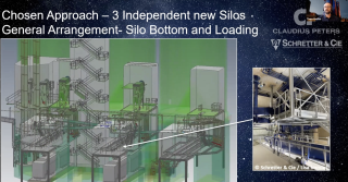
14 July 2022
13 July 2022
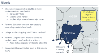
12 July 2022
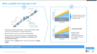
12 July 2022
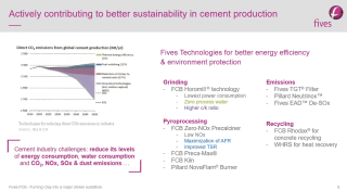
12 July 2022
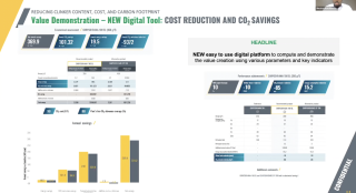
12 July 2022
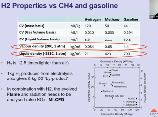
12 July 2022
12 July 2022
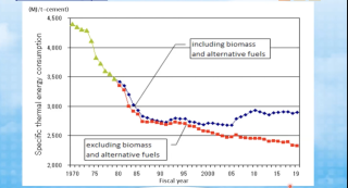
12 July 2022
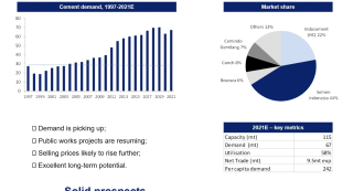
12 July 2022
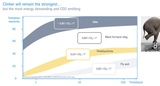
12 July 2022
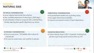
12 July 2022
12 July 2022
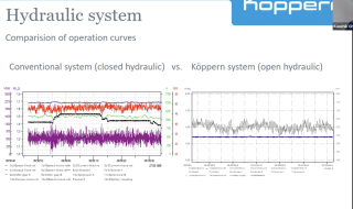
12 July 2022
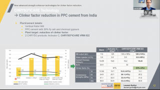
12 July 2022
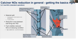
12 July 2022
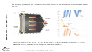
12 July 2022
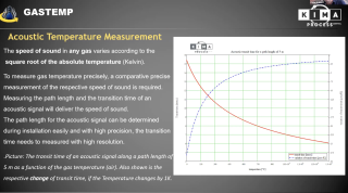
11 July 2022
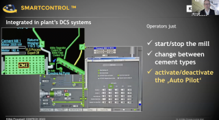
11 July 2022
11 July 2022
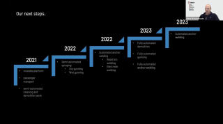
11 July 2022
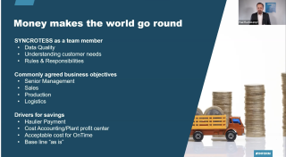
11 July 2022
11 July 2022
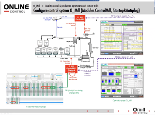
11 July 2022
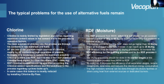
11 July 2022
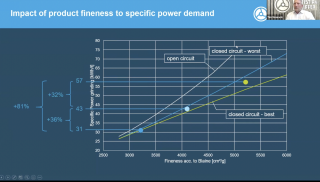
11 July 2022
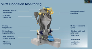
11 July 2022
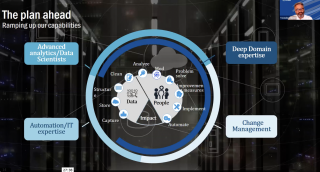
11 July 2022
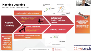
11 July 2022
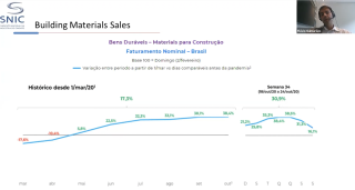
11 July 2022

11 July 2022
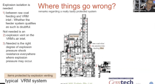
11 July 2022
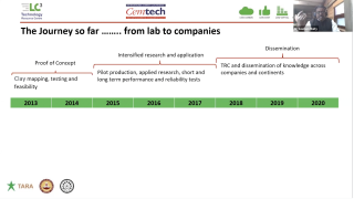
11 July 2022
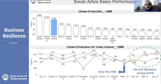
11 July 2022
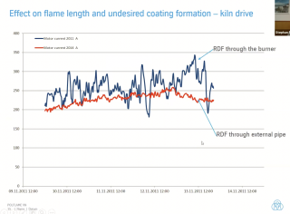
11 July 2022
11 July 2022
11 July 2022
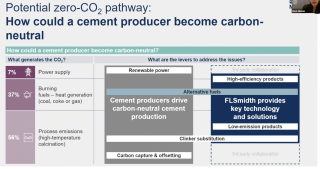
11 July 2022
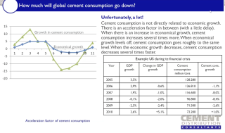
11 July 2022
11 July 2022
11 July 2022

6 July 2022
1 July 2022
1 July 2022

8 June 2022
12 February 2021
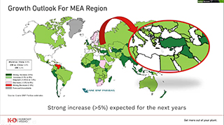
12 February 2021
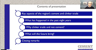
12 February 2021
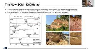
12 February 2021
12 February 2021
12 February 2021
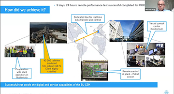
12 February 2021
12 February 2021
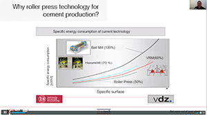
25 September 2020
25 September 2020

25 September 2020
25 September 2020
23 September 2020
22 September 2020
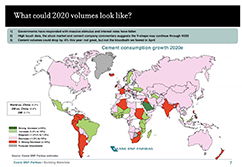
22 September 2020
21 September 2020
20 February 2020
10 February 2020
10 February 2020
10 February 2020
7 February 2020
27 January 2020
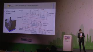
23 January 2020
23 January 2020
23 January 2020
23 January 2020
2 May 2019
30 April 2019
18 April 2019
18 April 2019
18 April 2019
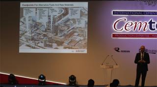
12 April 2019
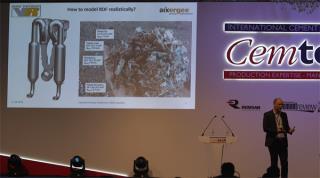
12 April 2019
11 April 2019

10 April 2019
10 April 2019
10 April 2019
9 April 2019
9 April 2019
4 February 2019
17 January 2019
31 July 2018
31 July 2018
31 July 2018
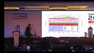
27 July 2018
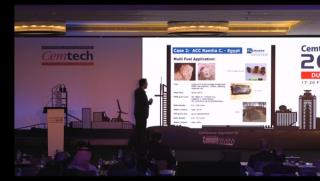
27 July 2018
27 July 2018
27 July 2018
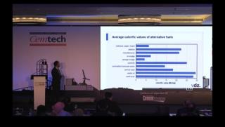
27 July 2018
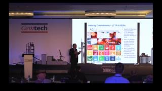
27 July 2018
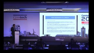
27 July 2018
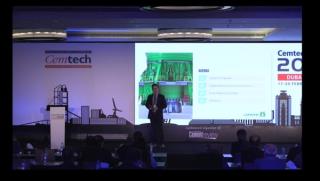
27 July 2018
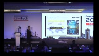
27 July 2018
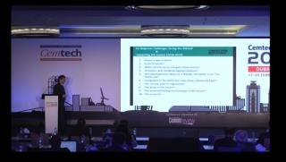
27 July 2018
25 July 2018
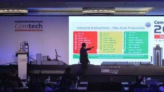
25 July 2018
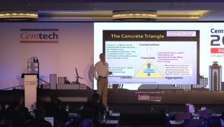
25 July 2018
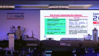
24 July 2018
24 July 2018
24 July 2018
23 July 2018
23 July 2018
23 July 2018
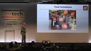
20 July 2018
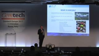
20 July 2018
20 July 2018
20 July 2018
20 July 2018
20 July 2018
20 July 2018
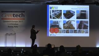
20 July 2018
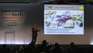
20 July 2018
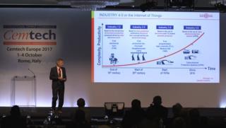
20 July 2018
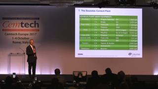
20 July 2018
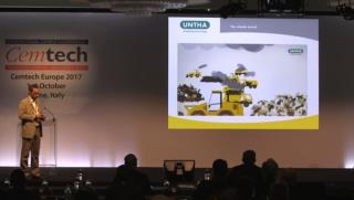
20 July 2018
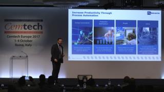
20 July 2018
20 July 2018
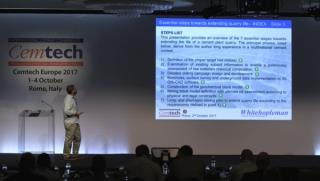
20 July 2018
20 July 2018
20 July 2018
20 July 2018
20 July 2018
19 July 2018
19 July 2018
19 July 2018
19 July 2018
19 July 2018
23 March 2018
23 March 2018
23 March 2018
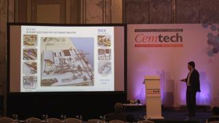
23 March 2018
23 March 2018
23 March 2018
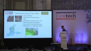
23 March 2018
23 March 2018
23 March 2018
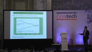
23 March 2018
23 March 2018
23 March 2018
23 March 2018
23 March 2018
23 March 2018
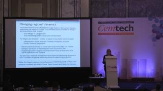
22 March 2018
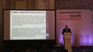
26 October 2017
26 October 2017
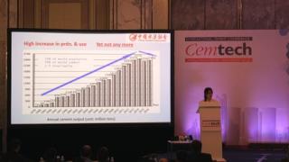
26 October 2017
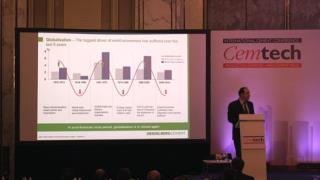
26 October 2017
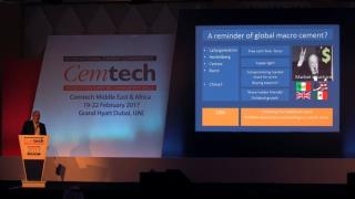
14 August 2017
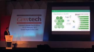
14 August 2017
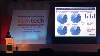
14 August 2017
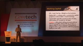
14 August 2017
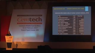
14 August 2017
14 August 2017
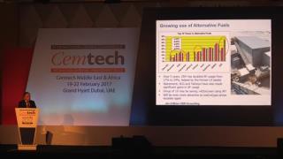
14 August 2017
14 August 2017
14 August 2017
14 August 2017
14 August 2017
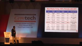
14 August 2017
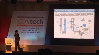
14 August 2017
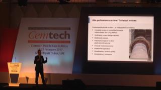
14 August 2017
18 July 2017
18 July 2017
18 July 2017
16 June 2017
16 June 2017
16 June 2017
16 June 2017
16 June 2017
14 February 2017
14 February 2017
14 February 2017
14 February 2017
14 February 2017
14 February 2017
14 February 2017
14 February 2017
14 February 2017
14 February 2017
13 February 2017
13 February 2017
13 February 2017
19 January 2017
19 January 2017
17 January 2017
17 January 2017
17 January 2017
6 January 2017
18 August 2016
18 August 2016
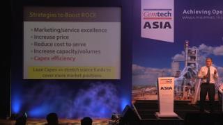
18 August 2016
18 August 2016
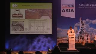
17 August 2016
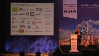
17 August 2016
17 August 2016
16 August 2016
16 August 2016
16 August 2016
12 August 2016
12 August 2016
12 August 2016
11 August 2016
11 August 2016
11 August 2016
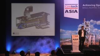
10 August 2016
10 August 2016
10 August 2016
8 August 2016
8 August 2016
8 August 2016
6 May 2016
6 May 2016
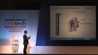
6 May 2016
6 May 2016
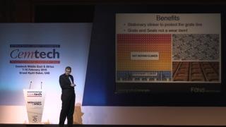
6 May 2016
6 May 2016
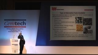
6 May 2016
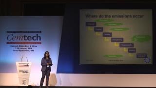
6 May 2016
6 May 2016
6 May 2016
6 May 2016
6 May 2016
6 May 2016
6 May 2016
6 May 2016
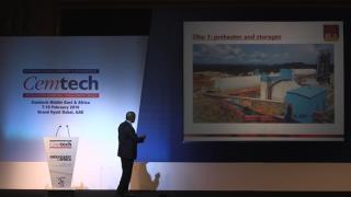
6 May 2016
6 May 2016
6 May 2016
6 May 2016
6 May 2016
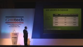
6 May 2016
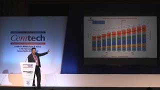
25 April 2016
25 April 2016
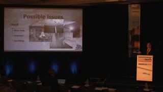
11 March 2016
11 March 2016
11 March 2016
11 March 2016
11 March 2016
11 March 2016
11 March 2016
11 March 2016
11 March 2016
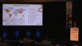
11 March 2016
11 March 2016
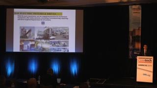
11 March 2016
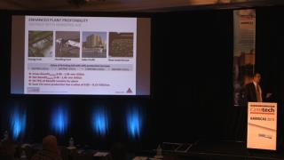
11 March 2016
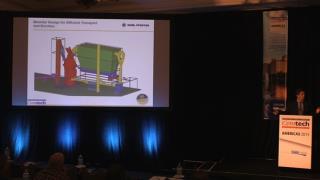
11 March 2016
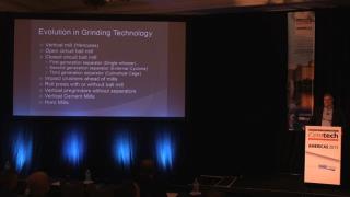
11 March 2016
11 March 2016
11 March 2016
11 March 2016
11 March 2016
11 March 2016
21 December 2015
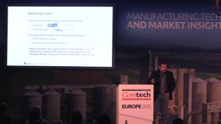
15 December 2015
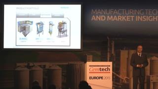
15 December 2015
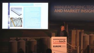
15 December 2015
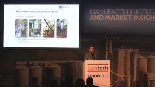
15 December 2015

15 December 2015
15 December 2015
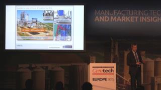
15 December 2015
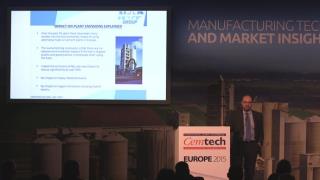
15 December 2015
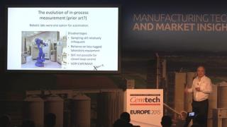
15 December 2015
15 December 2015
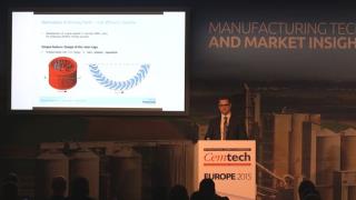
15 December 2015
15 December 2015
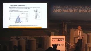
2 December 2015
2 December 2015
2 December 2015
2 December 2015
2 December 2015
2 December 2015
2 December 2015
2 December 2015
2 December 2015
2 December 2015
2 December 2015
2 December 2015
21 August 2015
21 August 2015
21 August 2015
21 August 2015
21 August 2015
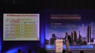
21 August 2015
21 August 2015
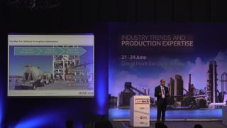
21 August 2015
21 August 2015
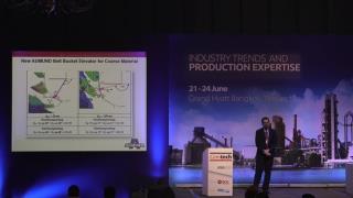
21 August 2015
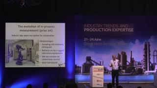
21 August 2015
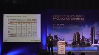
21 August 2015
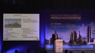
21 August 2015
21 August 2015
21 August 2015
21 August 2015
21 August 2015
21 August 2015
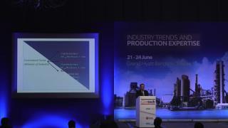
21 August 2015

21 August 2015
20 August 2015
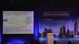
20 August 2015
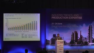
18 August 2015
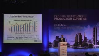
18 August 2015
18 August 2015
18 August 2015

30 June 2015
29 June 2015
29 June 2015
29 June 2015
29 June 2015
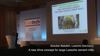
29 June 2015
29 June 2015
29 June 2015
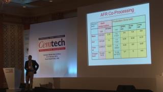
29 June 2015
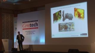
29 June 2015
29 June 2015
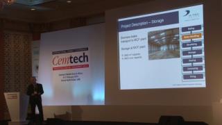
4 June 2015
4 June 2015
2 June 2015
2 June 2015
2 June 2015
2 June 2015
29 May 2015
29 May 2015
28 May 2015
28 May 2015
28 May 2015
18 February 2015
17 February 2015
13 February 2015
13 February 2015
Try searching for another title.