
2 September 2026
This transcript was generated automatically and may contain errors.
Welcome to Cemtech. our webinar for March 2024. Delighted to be here today for our third webinar of the year. My name's Thomas Armstrong. I am the managing editor of International Cement Review, and I'll be hosting this session on alternative fuels. We've had I can't believe it's already March. we've had two sessions already this year. We looked at carbon capture in January and grinding in in February. Now we're we're gonna take on one of the most popular themes of the year, I think which is Alternative Fuels. and as you can see, we've got a lot more lined up for you later on in the year. many of you know us already, but if not we are a monthly publication.
it's a subscription publication you need to subscribe to receive our, our magazine. But each month you'll receive a hard copy of International Cement Review and all the latest information news updates on new technology articles, plant reports and much more. So take a look for more information on cnet.com. if you subscribe, you'll have a choice of handbook, including the Cement Plant Operations Handbook, our Essential 300 page handbook to guiding you through the operations of, of the cement plant. It's a great reference used all over the world and on many training courses. please take a look again on our website for more, more information.
or you may Chi Choose the Cement Plant Environmental Handbook which has a section on alternative fuels production and utilization. But but 40 or 50 articles looking at every aspect of cement manufacturing. please take a moment to visit cnet.com and you'll find more information there. this year we've published the Global Cement Report. It comes out every two years and is a comprehensive survey of the cement industry. We profile around a hundred seventy, a hundred seventy five countries and provide UpToDate statistics, forecasts database of cement plants a whole a whole array of information. if if you need to find out about the cement industry in any country this is your starting place.
and there's more information on cement.com/gcr. 15. A quick look at forthcoming events in-person events will be in Asia returning to Jakarta. we were last there, I think in about 2012 one of the biggest markets in Southeast Asia with about 140 million tons of capacity. we'll have our usual two day event intensive conference sessions with presentations and panel sessions, and a very large exhibition. I think we have around 50 exhibitors taking part this year in EC Asia. please take a look at our website and you'll find more information on how to participate and register. That brings us to today's webinar which is on the preparation and burning of alternative fuels.
really as I, as I mentioned in the, in the opening, this is one of the most popular themes that we that we engage in on our webinars and for good reasons. It's one of the most effective pathways to decarbonization. it's a really key lever. burning alternative fuels also offers multiple benefits to society in terms of waste management reduced landfill helping to tackle also the issue of methane production from landfill and many other benefits. but of course, we're here to, to look at the, the burning and use of alternative fuel in cement plants. alternative fuel utilization rates really depend on local conditions.
it it depends on your waste streams that, that you can have access to the regulatory regimes that are in your, in your particular country. and we know there's a, a massive range of utilization levels from, from zero for companies that are just burning fossil fuels all the way up to a hundred percent in some of the more advanced plants in Europe where the high cost of landfill really stimulates alternative fuel utilization. So there is a huge range. but in this webinar, we're gonna be looking at the technology solutions from preparation of municipal solid waste into the fuel all the way through the combustion technologies be looking at some successful technologies now available.
and we have a really excellent panel with us today to help us explore these themes will be looking broadly at the role of alternative fuels. Joel Meyer from FCT Combustion has a great knowledge of the sector and, and we'll look at the, the broad picture. But before then we'll have details on how to produce alternative fuels or RDF from municipal solid waste from Eggman. And we'll be looking at one of the key solutions on offer in the market, the pyro rota combustion chamber on offer from KHD in Germany. so really it's time to, to get on with the, the show. we're gonna start with Eugene Becker from eggman and lba in Germany.
Eugene, if you'd like to start sharing your, your slides, and I'll just give you a quick introduction. by the way while you are listening to these presentations you can see a q and a button on your zoom in interface. If you just press that and just type in any questions you might have, we'll try and tackle them after the presentations. but here we have now Eugene, he's currently business development manager, Eggman responsible for Eggman fuel process. His previous roles include project sales manager at TIS and Crop Industrial Solutions where he covered CIS countries specializing in the development and acquisition of mining project projects.
He also spent four years at Christian Pfeiffer as a process engineer, commissioning, grinding plants and countries, including Saudi Arabia and Ghana, and lots of exotic locations as well as supporting the optimization of existing plants worldwide. so a really good background in the sector. very pleased to be able to welcome Eugene's. Gonna talk about the economic conversion of MSW into RDF. Over to you, Eugene Thomas. Thank you very much for the warm introduction and welcome everybody to this great webinar. So, as Thomas said, I will give today a presentation about economic way to con convert Ms. W into RDF.
And I would just start the presentation with one slide as to give an overview about the company. So the AGA one company is a group consisting of me different independent companies, and we have three main pillars main business pillars, so this is construction then the recycling technology. So where I'm dedicated to, so where we have all the technology to process waste mechanical in a mechanical way or biological way. And also we operating compost and biogas stations in Germany. we are around 1,200 people around the world, and I have a turnover above 200 million.
So the question what I would like to rise, so if we look in the strategy, the cement industry is going to is going right now to reach the net zero target. So, and one of the target is to increase the alternative fuel in the cement industry to decarbonize the cement industry. But the, the question will be what, in my opinion, that that in the next future, the demand for alternative fuel will rise dramatically. And the question will be, what will be the secured source to produce RDF?
And we from AGAs, one of the opinion that the household waste, which is available in huge amounts around the globe, is a good source and secure source to produce good quality RDF, but of course has our own challenges. But about the challenges I will talk about we'll talk later in this presentation, but to highlight a bit how the demand on alternative fuel will rise. I just put up a calculation here on this slide. So if this calculation is similar to one European cement operator, so it produce around 120 million tons cement worldwide, so it's around 3% of the global production. So if you, if I consider clinker factors, 0.65.
So I came to a clinker production around 78 million and taking the energy and tendency for clinker production, 3.5 gigaton. So I, I end up for 210 million and 364 thousand gig of energy, what is required. So, and this this in this case, so this cement plant operator or is replacing the fossil fuel by 23% by alternative fuels, but already now is committed to, to reach 45% in 2030. So when we look at the situation, so when there's cement operator right now is using or reaching 23% of substitution rate in 24, but want to reach 45 in 2030. So it means, so it increased almost by 95%.
sorry, I just have to, So, and it's appro approximately equivalent to 20 million tons of MSW, which can be converted in, into the, into the fuel to reach this amount of RDF, which is required by this sun cement plant operator to reach the 45% of substitution rate. And a country like Turkey with a population of around 50, 85 millions people generous around 20 to 30 million tons of MSW every year. So, and that's why we, from aga one of their opinion that MSW is a good source to produce RDF and to one ton of w contains sufficient energy to burn, to burn OneLink. But of course, the MLW need to be processed in the right way to enrich the caloric value.
And if, if we see the numbers right now, so globally, so we expect 2030 that the MSW generation will rise, and in the 2050, we'll reach around 3.5 billion tons of MSW around the globe. And and today the global cement capacity including China, is around 4 billion tons. So, so that's why we say there's enough MSW to pro produce enough RDF to serve to the to, to the cement industry and to provide enough RDF for the industry to decarbonize the cement industry by 2015. But of course we know all the challenges what the MSW has. So one of the main challenges, of course, the organic. So the organic is very wet and creates a high moisture.
So normally the initial start moisture of, of MSW is around 50 to 60% in, in main countries. And the reason for that is because most of the countries around the globe do not have separate collection of waste at home. So that's why the higher mode of organic is is inside the MSW. But there are technologies available to conquer this this challenges and to convert MSW in very good LDF LDF, including the organic. if we look here, this is a typical MSW composition. So it's, I would say it is weighted for 90% of the world. So if we, as we see here, that 55% is foot and green, so then 15% paper, cardboard, and, and 12% plastic, the rest are inlet materials, which are do not burn.
So what we see here that if we, considering the food and the green waste inside MSW, that we have around 80% of combustible material inside MSW. And and it helps of course to to increase the RDF field when we used also the organic and green waste from MSW. But on the other hand side, we also helping the municipalities, which are really struggling at the moment with the organic, because mainly the organic is dumped on the landfills whether then the organic is producing methane, geo methane, and this methane is then exposed to the environment and contribute to the climate change. to use this organic for compost is not possible because this organic is very polluted.
It has a, a higher amount of microplastic and also is polluted by heavy metals. So nobody will allow to use this kind of compost to use it on a agriculture maybe in a landscape, but also in landscape. not everybody will ac accept this kind of compost. That's why the question is what to do with organic to put the on the landfill where it's producing methane and contributes to the green to the climate change, or maybe to use it as a fuel. And this organic is very challenging so that therefore the right process and technology is needed to convert it also to fuel.
And as I said, that the municipalities are really struggling with with the organic, because one ton of Ms W has the potential of one or bit above one ton of CO2 equivalent because one, one ton of meeting is could be contribute 28 times more to the climate change than the within do. So this is a very common way of producing our they have today. So, so when the MSW arrives to the mechanical process plants for the process plant is dividing between solids and organic. So the solids are pro, pro processed further to RDF, so the recyclables are taken out and the organic and ends up on the landfills with producing with methane, and then also contributes to the climate change.
But this process has also some disadvantages as in the mechanical process where the organic is separated from the solids you cannot avoid that the organic sticks to the surface of plastics and is over carried to the RDF. And this over carried organic to RDF creates, creates also moisture in RDF. And this moisture is around 30 to 40%, what they have already seen in many countries where RDF has produced this way. And also, the bigger disadvantage of this way producing RDF is the very low landfill diversion. So from 100% of SW still ends up 80 to 85% on the landfills. And our proposal is to, to think further, to, to implement mechanical, biological process.
And with this way, so it'll be possible to incorporate the whole organic into fuel and at acceptable moisture content that at 20% of of RDF will be moisture. So also take out the recyclables. And big advantage will be that the material which goes to the landfill, because we'll not avoid material which has to be sent to landfills, but we can reduce it to the minimum. And this material, which goes to the landfill, is in enough material and already stabilized organic, which will not produce, maintain anymore on the landfill. And the big advantage of this process is that the organic is dried. You have low moisture in the fuel, so only in that material stabilized materials goes to landfill.
And a landfill diversion of 80 to 90% is reached with this kind of process, which is already proven in the market. And we, from AGA one developed a process. So we call it the process aga one fuel process. And this AGAs one fuel consists of three main steps. So we shredding the material, we bio drying the material, we refinement, we refine the material to increase the, to increase the caloric value, and then to produce high quality RDF some inner material and stabilize organic gold, the landfills. And of course, the recyclables can be taken out if it's necessary and then sold to to the market. And this process is scalable from 100 tons per day to 2000 tons per day.
So here you see so the pictures of the process, so main so the main step or the first step is to shred the material. So the main target is to open the bags to get the access to the material. So we are reaching after the shredder size 20 two 50 to 300 mm mm. And this all materials we sent to the bio drawing. So you see the picture in the bio drawing is taking place in, in base. And it stays for around 20 days in the base, and it's covered with me membranes, and the material is turned every five days to lose the material a bit and to exchange the layers to improve the drawing. But in following, following slides, I will explain more in, in more detail how the process is working.
And after the material has reached the 20% of rest moisture, it goes to the refinement plant where we taking all the inlet materials, taking all the stabilized organic and scent fines. So practically in the last step, we're enriching the caloric value. The bio drawing process is based on the compo compost process, and it's relatively new technology, but already proven on the market. So we have several references worldwide. but the difference between composting and drying is the, the, the objective of drying is mainly to reduce the moisture in, in the waste and to make it easier to, to separate later in the refinement step.
And the composting target is to stabilize the, to the material 100%, and then to use it as a fertilizer or compost for agriculture. Agriculture and what is happening in inside this process. So we have walls and then beside between the walls, we put the shredded waste. The floor of the base is aerated, where we're putting air inside by blows. And the waste is covered with the membrane as a special membrane, which is, which allows to breathe through, but do not allow to the rainwater can enter into the heap. And so when we introducing the air, so the microorganism are supplied by oxygen, and they start to digest the easy degradable material.
And in this process they are generating heat, and we are reaching 60 to 70 degrees inside the heat. And when the air is flowing through the, through the material, the air is taking up the heat and also taking up the, the, the water and the air is going through the membrane and takes the water or the steam with. And and also this membrane helps to reduce the order problem significantly because the outdoor cannot pass through the membrane. And this is purely biological process. We do not need any additional fossil fuel to generate the heat that the heat is is only generated by the microorganisms. And this is aerobic process. So during, during this process, no methane is produced.
And yeah, and all these emissions are with CO2 and nitro exigence. So this is a case from Mexico. On on the left hand side, you, you see the, the composition of the MSW. So they have had a lot of amount, a high amount of organic, and we play through one case. So when we have a plant with 300 tons per day, working seven days per week in one shift, so we came to the result that we could reach RDF 15 to 50 mm with the moisture below 20%, and the calorific per above 14 mega kg or 14 giga perton. And this is the mass balance from the case. So what is really clear here that the RDF field is really high because we incorporating the organic into the fuel.
So the, we are reaching 30, almost 37% of organic of the RDF field, so some recyclables. So it's mainly metals, because most of the time those scavenger are taken out. all the pea PET bottles or ppe, whatever. So defines this is so material is mainly sand and degraded organic, which goes into the landfill and heavy the stone glass. What we also taking out to improve the caloric value of the RDF. And so also the main portion is the mass loss. So because of the drying, because we, we evaporate the water out of the MSW. So, and the good thing, the fines can be used as cow material for the landfills, or also sometimes the cement plants are using it as alternative raw material.
This is the result from a plant we have in Iraq. So you see the RDF 10 to 50 mm, the plant is switching 14 to 16 gig perton. And the five here you see is below 10 mm. So it has also some color calorific value five to six mega per kg. But as I said, so one custom Iraq is sometimes using it as alternative raw material as his process. And also here on the right hand side, you see a table of the RDF quality. So with all the contents for it has co chrome and ash content carbon content. So you see that we, in this case, we reached 20% of mega caloric value. it is gross. Okay. Net carly value was 18 edge content below 20.
And also the sulfate and also the chloride content was in the acceptable range. So sulfide was 0.075, and the chlorine was 0.44. The whole machines of the process are supplied by gasman. So the toy is our primary shred. We using it, so, so it won't set set as 50 55. It's a slow speed shred. And so as I said, mainly to, to open the bags. And after the materials then shredded, we bring it by trucks into the, into the base with them, right in the, in the wire drying area. So this is one reference. So here we have supplied 22 lines, and as I said this ma the material has to turn.
And this material is done by our special machine con, so this con machine based on a compost turner machine because we have also buckles, this is our company where we providing mobile machines for compost turning. And this machine con is based on this technology. So what this machine is practically doing, so during the turning process the turning process is done by a, a shelf with shovels. and this machine runs dri drives through the lanes, it opens the membrane and put the membrane ba back on the hips, be behind the machine. So a to fully automatic process. So you don't need people who are uncover and cover the heat the lanes. yeah.
And this way we are reaching 20% of moisture in the, in the base. So afterwards, afterwards, when the material is dried, so we bring it by front loader to the receiving bunkers, we'll lose the material again after the receiving bunker goes through conveyors to three fraction screens. So then the first fraction is fines. So zero to 20 M goes to the landfills. Then below 50 M goes directly to the RDF storage and above 60 50 m, it goes to the wind system where we take out all the inner materials or stones and glass and afterwards goes to the French shred, and then after the fine shred to the RDF storage.
But the the last wind and fine shredder mainly depends on the requirements on of the RDF user or RDF offtaker. So if size of RDF accepted between 8,100 mm so that we can exclude then the fine and use the fine shreds for re shredding the material to reach the required size and of, in this way, of course, we can reduce the CapEx of the of the project because the out there projects are always very CapEx sensitives projects. And this is our reference in Iraq and Sonia, this plant is treating 1000 tons per day and producing around 300 tons of RDF every day.
And he, in this case, we have supplied the primary shredder and the, the bio drying and the refinements station was supplied by our competitor, but you can see it now, Landfills are pollute landfills Using the sound has gone from the video. If you want to comment a little bit on the images. Yeah, no, we still can't hear Audio first, make the content accessible PowerPoint reduce weight. Well, you see that with this kind of technology, you can achieve many goals. So you have very good RDF quality, you, you help to con conquer the climate change. you are, you are also helping to reduce the CO2 emissions.
And what also important to say that when you are incorporating the organic into the RDF, so you also increasing the biogenic carbon content in the RTF, what is then really CO2 neutral And we believe, so with this AGA technology, we have something that is helping the cement industry, but also the municipalities to reach the goals in the future. So, and if you have question, just ask, I'm happy to answer it. Oh, sorry. Okay. Thank you, Eugene. that was a really nice presentation. We couldn't hear all the sound on the video actually, but the vi the images okay, were, were very were very, very clear. it's a big operation that's that that you showed from, I think Nia in, in Egypt. in Iraq.
Iraq Stan. Yes. Yeah. so yeah, there are a few questions that have, that have come up. I'll try and put a few of them to, to you. Now one is looking at the the, the heavy metal content. is that an issue? how high is the mercury content was one other question. what, how, what is the approach to contamination with heavy metals in, in your process? Okay, so what what we found out that the, they heavy metal content is aerates in the, in the fines, so in the zero to 20 mm fraction, and as we are taking all this fraction by screening, so that's how we're reducing the heavy metal contamination. Okay. So you you also have testing, I guess, of the final RDF which is also the, the final screen. okay.
Yeah. And that's an actual example then. Is it from the, from The, this is the example from the Iraq plant? Yeah. Good. Okay. in terms of moisture content you, you talked about getting the moisture content down to 20% and there's the comment saying, well, that's too, still too high for a normal pyro process. I, is that the operational norm for you, or, Yes. the, the thing is that I said there's a technical limit for the bio drawing 20%. Of course, you, you could, you could keep the material longer in the base that, so we, maybe we could reach 15, but you know, the, the time from 20 to 15% is that long. It would not be reasonable from the economic economical point of view.
But what we know from our customer in Iraq, so the, that the cement plant is happy with this RDF and 20%, of course when we talk about RDF for the main burner, then 20% is high, but this kind of fuel we are producing is mainly sign of fuel introduced through pyro or hot disk from other companies. So that's why we do not see this is a critical point of 20 percent's not allowed too high for the combust combustion process. Okay. So you, you are aiming the, the, you are aiming for combustion systems that are for systems that have combustion chambers rather than firing through the main burner. Exactly. Yeah. Yeah. Okay. alright. So that, that takes care of, of those two questions. what else?
We have questions about the the membrane. What is the cost and, and what is the maintenance of the membrane? I guess there's a question about the cost of the whole yeah. System. and also about the maintenance of the membrane itself. It is very key to the process. Mm, Yes. Right. So the membrane is one of the main components of this bio drying. And this is the ving technology is our knowhow. So we are, we're not producing the membrane, but we have suppliers who producing this membrane according with your specifications and the, the maintenance. So of course, it can happen that somebody make a hole in the membrane, but then you can patch it.
So there's some maintenance available what we have, but the lifetime is two to three years of the membrane. Okay. But the, the cost of the system, of course, it'll depends on, on many factors, but I would say it's difficult to say here what the price will be, so it can be evaluated and specifically in a project. Okay. But, but maybe to make it to give some numbers. So, so it around between eight to 12 euros per ton, what you need of CapEx and operation plus is that, that's for the, for the membrane or For oh, for the whole drying system. Okay. Right. then there's a, a question about actually setting up, constructing, delivering a, a, a a the, the whole process. how does that happen?
Does it happen with an EPC contract? what kind of what kind of ways do you have delivering a the whole system? So we, we not do, we do not PC contracts but we have possibilities to have come into a consortium or find a partner in the country who will take care of the concrete part. And we will be the purely the technology provider and who will give the warranties for the RDF because we also give warranties to the customer that our process will reach certain quality in terms of size and what the content. Okay. a couple of questions just asking, why are you not separating more of the organic component in the, in the MSW? can you address that?
So we're not supporting the organic because of we want to increase the RGF field because we, of the, of the opinion that the organic is also a good RDF because it's because it's biogenic carbon content. So it's CO2 neutral, so that helps to, to reach the goals of the cement in, of the cement industry. And also it creates a lot of problems on landfills. So, and then why to send something to a landfill when it can be used as something usable. Okay. there's also that question about biogenic content, which you just raised. and we, you'll remember when we're in, in Dubai Mm-Hmm. Or, or a few days ago at Cemtech there was a discussion of CAM mm-Hmm.
And whether the biogenic non biogenic components would qualify under the CAM regime. can you comment a bit on that for producers who are, are considering that aspect of it? Yeah, of course. So at, as according to my knowledge at the moment is using alternative fuel as a CO2 nutrient as at home at all. So it means so if you burn rubber, if you burn plastic, so you claim as a CO2 neutral, by fact, it isn't, it is, it's not CO2 neutral because it's it's fossil carbon. And and I'm of the opinion that this rule will change in the future.
So that fossil carbon from alternative fuel will be not CO2 neutral only carbon biogenic carbon will be considered as co neutral because by fact, it is only CO2 neutral only biogenic carbon con content. And the, the good thing is, so when the, the bio when the organic is not sent to the landfills and used in the RDF, so we increase the biogenic content in the RDF and also saving CO2 on the landfills, what can be then transferred, what I have heard that the GCCA is working or planning to transfer the CO2 emission savings from the landfills on the account of the cement plants.
And this will be really a game changer then for this process because it'll really help to, to reduce the CO2 emission of the cement plants by burning fuel. Very good. Well, that's all we have time for now, Eugene, thank you very much for, for a, answering all the questions for your presentation. There's a lot of interest. Please go to the q and a and maybe answer some of the questions that we haven't been able to to Okay. Will do on now. But for now, that's Eugene from Eggman. Thank you very much. You're welcome. Fantastic. Well we're gonna move on to our second presentation. We, we, we talked a little bit about combustion chambers and, and now we're gonna hear more.
I'm very pleased to welcome Ys Yen's brighten back from KHD in Germany. Ys, if you'd like to start sharing your presentation Ys brings with him almost 20 years experience in the cement industry during which time he's commissioned a multitude of challenging projects. he's also been responsible for numerous feasibility studies, audits and process calculations. Today, he's one of the leading minds behind PhD's research and development projects in the field of pyro technology. And since 2019, he's been head of the company's pyro systems department. he's spoken here before on Cemtech, and we're really pleased to have him back. And he is a, a real expert.
And today is going to talk a bit about the pyro rotor. So Ys over to you. Thank you very much. Thank you very much. Do you, do you understand me? Yeah. And we can hear you. Okay. That's all good. And can see too. Thanks. So Thanks Thomas for the nice introduction. Thanks, Oregon for the very nice presentation. So today my topic is about our success story on alternative fuel utilization. our KHD, so-called power rot. my name is Rebar as already introduced. I am head of pyro systems department in KHD. So let me start with a content of my presentation. I would like to give you a very brief overview about the company I'm working for, KHD about some challenges when firing alternative fuel.
after this I would like to introduce you our combustion chamber, pyro rotor, some mechanical features, some process features. I don't go too much in detail of the, of the process, but at least some slides regarding operation sizes and references regarding power, water, what is available from us to the market. And my third big topic is a case study we did in South Korea with one of our client regarding a modification project by implementing pgo GoTo in the cal. Last, but not least a summary of my presentation. Okay. KHD as a supplier. KHD has a lot of experience more than 160 years in the, in the cement industry. from yeah, request for concepts until commissioning, we can supply everything.
What is needed for cement production. We are a market driver, and of course, we are focusing on the requirements of the markets. And as you know a lot of focus nowadays is on decarbonization of the cement. Yeah. And this is a one big topic in our daily work. Yeah. So globally, KHD head office is based here in Cologne, Germany. We have a lot of entities subsidiaries, for example, the biggest one is in New Delhi, India serving our very good market in the subcontinent of, of India and some countries. at the border of India, we have one entity in Atlanta, us in Beijing China, and in eastern part of Germany in desal. But with this, we have a a very good market setting all over the world.
And more than 700 workers are serving the cement business all over the world. So coming to, to my responsibility as a full liner of supplier, KHD can provide from the query to the packing station, a whole cement plant. But with our own technology, the so-called Prop Coty equipment, we are just supplying mill systems grinding stations. And my responsibility is the pyro section means everything which is related to the kiln and the upstream and downstream equipment like pre heaters, calsus burner technology, bone clinker coolers. And in this, of course, we are also focusing a lot on the decarbonization of the product.
And one topic is of course, to reach some global goals, the alternative fuel, when we talk alternative fuel, of course, there are challenges. Some challenges are already mentioned by Mr. Oregon. in the previous presentation, I don't want to go to all challenges, but of course you have an influence in energy balance. The overall heat demand might be increased due to the higher volume in the system. You have an influence on plant operations, stability and availability. lifetime of refractory, for example, coating tendency within the system. the clinker quality can be affected negatively, also positively, it depends on the type of alternative fuel.
And of course it has an influence on the emission concerning what kind of alternative fuel you are intending to fire. One big challenge Mr. Ogen already mentioned it, is the preparation of alternative fuel. Of course, we have the, we have this huge landfill areas. In some markets. We have huge amount of unprocessed alternative fuel. And to fire this to a standard kiln line, to a standard Cal Sinai, of course everybody has to think about preparation. Yeah. And to shredder, to homogenize to, yeah. To prepare your alternative field that it's suitable for a standard kiln line. We as KHD, have one product where we try to avoid or at least minimize this preparation step. Yeah.
And this we did with our, so-called combustion chamber solutions. Yeah. We have a standard combustion chamber, which is called pylon r combustion chamber, which is limited in particle size, limited in in the type of alternative fuel. And therefore we invented the pylon r Yeah. This table gives you an overview what is possible in terms of physical property of your RDF while thinking of using different kind of feeding points of the alternative fuel. Yeah. But today my, today's presentation is focusing on here, on the left sorry, on the right hand side solution which can consider a very high particle size, a very lumpy alternative fuel material.
So about the pyro rotor mechanical features, I would like to introduce some points. It's very similar to a standard kiln in the cement process. Yeah. And this was the target of our engineers, that we have a simple and robust machine, which is, which is proven in the production maintenance teams all over the world can handle this features like this bearing this ceiling and the drives of such a device. And this is why we copied a lot of engineering features from a standard KHD rotary kil while bringing this product in the market. Yeah. If we go in detail here, we have the rotating drum, the so-called pyro rotor itself.
We have an inlet chamber, which is also very, very similar to a standard kiln inlet chamber. We have a connection to the tertiary air. We have a standard tertiary adduct and the alternative fuel feeding shoot. So the pyro rotter itself, it's driven by a friction drive, so we don't have a gersky opinion drive, which provides you less maintenance. We have two electromechanical drives at the pyro rot, rotating the pyro rot. We have a a rotating fixation of the tire, which is standard in KHD design. We have a spring loaded inlet and the spring loaded out outlet avoiding a false intake into the pyro rot. so a very common design copied from A KHD kill.
Now coming a little bit into the process engineering, the PY water, what you see here in the, in the center of this slide gets partly the tertiary air from the cooler. This can be controlled by a damper with the tertiary air. We introduce the alternative fuel inside the pyro water. The alternative fuel gets dried, the rest moisture will be dried. Of course, then with a setting of the teter air, we can firstly shift all the material, which is flyable towards the calina duct. What, what you see here, and everything which is not flyable, ends up in a surface of the pyro rot. So by rotating the pyro rotter, this material has a long retention time.
And during the retention of the material inside the pyro rotor, you create some ling gas by partly combusting this material, this ling gas mainly containing carbon monoxide will enter the calina and properly burns out in the calina with the rest of the tertiary air coming from the ary air duct. Yeah. The final combustion can take place all of this lean gas and the combustible metal inside the calina. And the big advantage in this pyro water is the very long retention time. Up to 10 minutes. Yeah. And the rest is well known. We have an inlet of the bottom of cyclone.
The precal sign material is entering the kiln, and the unsign material coming from the second lowest cyclone of the preta tower is entering the cal sign. So no raw material is needed in the Otto itself. The combustion is just controlled by the amount of hot tissue air entering the Otto. So for highlighting the operating principle, I would like to share some animation with you. I hope this will work. So here you see an animation of the pyro water. Now it's cut it, you see the Chet air entering the pyro water. And here we have double gate entering the RDF material. You can even introduce to the py wall to whole car tires.
And by this you have this by rotation you have this constant surface building from the fuel to the combustion air coming from the TAD. Yeah. So this is the idea. As you see here, some flyable material is entering the cal sign and the, the, the, the non-combustible very cause ash is falling just into the kil inlet and formatting with the mineralogical phase. The clinker, yeah. So now I would like to give you some references and what is possible in sizing of this pyro water device. KHD can provide from 2.8 diameter to 4.2 diameter. And our r and d department is already working on five meter dire pyro or size.
The length is depending on the, on the mass flow of alternative fuel from 10 to 50 meters. Yeah. So all of these sizes are equipped with two supporting rollers. as I said before, both rollers are driven by electromechanical drive. The drive is very small compared to a, to a kiln drive. Yeah. For example, the 3.4 times 10 meter pyro rot just need two times 18.5 kilowatt. it's just a very small motor, which is not a considerable high electrical power consumption of your klow nine. The rotation speed is, can be controlled by VFD from 0.8 to three point zero RPM. And here you see a reference list. All the was sold in the past.
So the success story began in 2017, and we just received another order from one of our Chinese client. and as you see, the main driver of this product was in the market of South Korea. Therefore, I would like to highlight now some South Korean project in general, and one South Korean project detail. So here, also some map where the location of this 11 South Korean projects are located. So, for example, one is in san plant in dong hay, where we realized substitution rate on the cal up to 87%. This was proven during per performance guarantee test. This means on this on this killing size means a mass flow of alternative fuel of up to 25 tons per hour. the success store and client was very happy.
Therefore, we even installed in a, in a second line of this client, another pyro water with the same size. And then the success story continued in dong hair and Kline four where we even provided a new clinker cooler. And here, as you see, unfortunately, we did not met the substitution rate, but the limit was the mass flow of the of the alternative fuel. Yeah. Due to the high moisture and the low calorific value, we could, we could not achieve this high term substitution rate because the mass flow was limited. And as I said before, the mass flow is, or the size of the pipe water is related to the mass mass flow. So now I would like to draw your attention on one case study.
This was also in South Korea, in Asia, cement in on K nine number three. and with this example, I would like to explain you how this client and KHD executed the project. Yeah. So first of all, there was just a, an existing drawing with an idea with a business case from the client. So the client, of course, the business case was to fire a high amount of alternative fuel to, yeah, to reduce the the, the production cost in terms of fuel costs, and of course, reduce the carbon dioxide footprint related to the thermal input of the, of the KI nine.
With this existing drawing, we made a proposal, and of course, we sent our engineers, our process engineers to site executing a plant audit, collecting a lot of process data, see what is the desired clinical quality, what is the possible alternative fuel quality. And with this, we provided the proposal drawing. We sent engineers to do a scan of the entire existing system. It was an old system supplied, I guess from a Japanese supplier. And according to this point cloud, we performed a collision model. And according to this collision model, we implemented our arrangement. And as you can see here on the right side, everything which is in brownish color is existing equipment.
And everything in this blue color is new equipment supplied by KHD. So as you see, we have a new cal duct entering the bottommost cyclones. Two new cyclones were supplied, and here in the middle you could, can see with the connection to the existing terje air duct, the pyro water installation. Yeah. This was our final ar arrangement. By implementing this after detailed engineering, you could can see the, the executed project here on the left hand side. On the right hand side, there is a detailed picture of the pyro water. And during commissioning, we could achieve this kind of alternative fuel, so mainly rubber. So 3D material was fired.
This 150 3D material, some higher quality, hard plastic, 100 millimeter in 2D. Yeah. And to control the temperature after the calci, we had to fire a small amount of soft plastic of this very high quality RDF. But with, with this three RDF materials, we could reach this goal, or this business case was fulfilled by the client to fire 85% alternative fuel in this K nine. Number three. Yeah, of course. Here some screenshot with some operation data. At the first glance, it looks like a kiln, but it's not a kiln. It's the, you see the temperature of the ings.
You see the temperature inside the pyro rotor temperature of the calina feeding system of of the RDF and the setting of the tey air damper in total here in this project the operator has to control the tey air with three dampers. One damper is going directly below the pyro water. One damper is control the te tey air to the pyro water, and one is to have a little bit of stage combustion to reduce further the NOx emission. Yeah. So as a summary, the pipe of water gives you the highest flexibility in almost any type of unpro alternative fuel. Yeah. from the truck of, from the landfill, you can directly fire the material. Yeah. So just special type of alternative fuel has to be pre-processed.
it, due to the very high retention time, it gives you a very high flexibility in the in compensating of quality of the alternative fuel. Yeah. This is one big goal. It definitely reduce the primary fuel cost. Yeah. So coal gas and heavy fuel are definitely, can be reduced. This can reduce also the fuel related CO2 footprint. It's ready to fire, as I mentioned before, to fire any type of fuel, even for future market or some changing in the, in the market of alternative fuel cement producers already. It's easy to operate, as I said before, just by adjusting the TAD amount and maintenance, like in a regular kiln.
And it can be retrofitted in any plant, doesn't matter if it's supplied by KHD, if it's a greenfield plant or a very old existing cult Zina. And the success, especially in South Korea reflects our, yeah. Our success in this product. Yeah. So I would be happy to answer questions, so if there are any questions. Okay. Thank you very much, Jens. And there are lots of questions. Okay. And I'll I'll ask you a few and then you can probably take over typing because every imaginable question has been asked really interesting lots of engagement with this piece of equipment. more generally, what is the maximum thermal replacement of the PY rotor? I see, I see you said 85%.
Is that the PY rotor or is that the whole system? It is just the cult fuel. Yeah. So usually the split from cube to cult is 60% at, at Calina. Some in some markets it's even more like India 40% at the kiln. So we try to, or our clients try to substitute almost a hundred percent of the catina fuel with this device. yeah. Yeah. Very good. So up, up to 60% of the yes, the prior process, which is If you want to further substitute, of course you have to think about firing RDF at the main burner. And for this, of course, as mentioned by Mr. Oing, this has to be higher pre-processing rate. Sure. Good. what is the maximum RDF humidity that can be fed into the pyro?
So usually without any additional burner inside the pyro rotor, there is no limitation by the humidity. The humidity is just, or the amount of water in the RDF is just limiting limitation is just by the ID fan. Yeah, of course. If the ID fan is well designed and for this upset condition, we can even fire up to 40, 45, 50% moisture. Yeah. But we are a little bit conservative when it comes to minimum net calorific value. And here I would not go below 2,800 kilo cals, 3000 kilo cals as total. Yeah. Otherwise we need an additional burner inside the pyro water. This is possible, but of course of, because of the high moisture, the, the calligraphic value will be reduced.
And here a limitation is around 3000 kilo cal per kg. Okay. And there was a question about the ID fan, but you've kind of touched upon that there is an impact Mm-Hmm. And obviously you have to work within the parameters of your, of your equipment and of your ID fan. Yeah. good. interesting question. ara regarding the discharge end of the equipment, which is wide open to the riser duct, what are the practical challenges during operation if an un imbalance of the draft causes a reverse gas flow backwards through the PY rotor? So if you have some very cause particle Yeah. Which is not burning.
This can be, for example, a can or some metal piece, this definitely will not go in the, in the in the calci as flyable particle. This will enter the kil inland. But we ensure by sizing the pyro water that all particles are fully burned out when exiting the pyro rot means our clients do not face any problem with carbon monoxide in the kil inlet. Yeah. This for sure. Okay. Very good. there really are, there really are a lot of questions here. I'm gonna, we're gonna leave it for now and move on to our next presentation. But Yen's a very, very good presentation. It's a really interesting solution. thank you for ha re representing it here.
and if you have asked, asked a question, I'm sure Jens will try and do his best to answer in the q and a. otherwise thank you. Thank you very much. Yeah, very much welcome. I try to answer in the chat. Yeah. Great. Okay, we're gonna move on to Joel Meyer from FCT. welcome Joel. it's good to have you back. Joel graduated in mechanical engineering with a, a focus on thermo fluid dynamics in 2002 in Brazil and an MBA followed in 2015 in a joint educational program between Austria and the USA since 2001, he's held a number of roles working on projects across more than 70 countries but always related to combustion and energy intensive industries such as cement, lime, steel, and other minerals.
He joined FCT in 2016 where he's now CEO based at the company's European headquarters in Vienna, Austria. And he's gonna talk to us about decarbonizing cement production, the role of alternative fuels. Over to you, Joel. Hello? Hi, can you hear me properly? Yes, sir. We can hear you. Yes. Very good. So thank you for the introduction today. The target is to talk a little bit about the alternative fuels in the decarbonizing the cement production. I would like to start, first of all, giving an overview. So we start here, once upon a time, there was a planet called Earth. there are some people living on it. And then these people more, more and more.
And today we are around 8 billion people, right? it's expected that by 2050 we'll be 2 billion more, and this 2 billion more. This means roughly one New York size amount of people per month, new in the planet. And all these people will need infrastructure, how housing energy and so on. And this is this infrastructure is still 60% of it still needs to be built by the year to 2050. So there's although there's a lot already made today, there is still, the majority still has to be done. Obviously this growing in population also brings some, some challenges for, for the planet. So this means more infrastructure. This means more energy demands. This more means more construction materials.
And at the end, more natural resources are used for it. So what does this mean for us? So this all has a immense impact on the environment, especially global warming is a, is a problem that we all are facing these days. sorry, this jumps to the wrong slide. One moment, please. So there is a, can you see again? Yeah. So there is an immense impact on, on environment global warming, and then the, I dunno why this is not really jumping to the proper page. I try again. All right. And the question is, okay are we doomed? Is this the end of the times? the answer is no, but this answer no comes with a big if if we all do what, what has to be done when we say all it means as envi as individuals.
So if we look into the weight hierarchy pyramid, I think there's a lot we can do to avoid the environmental problems that we are, are facing these days. So everything we can do on the top of this pyramid is better than what we, we have to do at the bottom of it. So if we can reduce the use of some resources is better if we cannot reduce the use, we should try to reuse the, the, the materials. If we cannot reduce or reuse the materials, we should try to recycle them. And all this we can do as individuals very easily. we should obviously avoid the last step that is disposal because this is what is, is being in the environment for many, many years.
and it's a, a combined effort from everybody, and especially in terms of industry. That's where we all are working. today we, we are focusing on the repair and recover of materials to be reused as energy sources. For example, when you're talking about CO2 emissions it's well known that cement production is responsible from six to 8% of the mermaid CO2 emissions. here is a chart how this has evolved since the second World War until some years ago. So it has drastically increased. and when we look from the million tons of CO2 produced by the 17 industries industry, we can see that part of it is caused by process emissions.
So basically the majority of it is, is by process emissions, basically from the CO2, from the material. And here we can talk, for example, how to reduce it. We can talk about cosign clay. FCT is also working on, on the cosign clay business. But it's not in the topic of this, of this seminar after this conference. So this webinar, if you want more details about cosla, you can visit our website or send me a, an email and we can, we can schedule a meeting. And there's another part, the blue part is caused by fewer electricity emissions. And here for exa, one way to reduce it would be the use of alternative fuel. We all know this diagram the cer ology with the phases of, of the clinker.
basically there are two main sections here that should be highlighted. One first phase from the drying of the, of the, the raw material until the transition zone of the C is let's say a preparation phase where the, where the raw material is being prepared for the ization, and then a second phase that has a, a very strong influence in the ER quality. And, and later on, the cement quality that incorporates the clinker and the cooling. we need to make this division into these two parts because depending on which, which the alternative fuel will be used in a different way.
When we are talking about the first part, about the preparation part, the cosigner to, to choose an injection point of alternative fuel in the consigner is like choosing a house, right? When you want to buy a house, you always are worried how is the neighborhood, how is the, the environment around it? how is the transportation meanings around this, this area, and so on. And for the CALS center for injecting alternative fuel in the Cals center is the same. So h how is the temperature distribution in the CALS center? How, how is the oxygen contain in the, in the different areas? What's the velocity profile? What's the residence time?
So basically you are more worried about the, the flow characteristics inside the cosigner. And for this I think it's for example, to, to find the better position to inject your alternative fuels and, and be able to maximize it. one way to do this would be through a CFD study. We can also do some, this is a result from some of some CCFD that we made in the past. or this would be more for for alternative fuel that have a good aerodynamic cart, mean that they fly together with the gases. In other cases, when we are talking about complete tires and so on, we can talk about a PY rotor, for example, or some other type of, of combustion equipment that, that can deal with these larger particle sizes.
But for smaller particle sizes, that can, that can fly very well. A CFD study is a good way to, to check if the, an existing co-signer can deal with the intended alternative fuels, or if a necessary modification is necessary. An enlargement of the, of the cow signer is required, or modifications on the, on the top of the cosigner for a better mixing, and so on and so on. So this all can be done through CFD. This is also not covered by by this presentation today. Today we'll focus on the, on the kune. So, and then there's a difference when we are talking about the Kune it's we can make analogy to a sports car.
So my Italian friends watching now you all know this, this car choosing how, how to fire the alternative fuel in the Kuhn is more about performance. So if you would buy such a car, you would be worried about which power it has, how, what's the maximum speed how efficient aerodynamically it is how is how it can turn and so on. And it's the same about the burner, right? So if you're injecting alternative fuel in the Kuhn, you are worried about how much you can use, what, what are the mixing efficiency of this burner how you can control the, the particle the alternative fuel particle direction and so on to inject alternative fuel at the kung side.
That's the main topic of this presentation today. there are two main options. One would be to use a satellite burner in the kung hood. So if you can see here let me put here laser pointer. So if you can see here, so the alternative fuel, the satellite pipe would be positioned a little bit above the burner. So in the secondary air, and this is a good solution up to a certain point because the secondary air has the majority of the air required for the combustion, right? Both 95% of the air in the Q is coming through the secondary air. This is a zone with higher temp high temperatures. So we are talking about 900,000 degrees. However this region has a very low control and mixing.
you have a very low control over the mixing and then injection conditions on the secondary air. The second option would be to use a modern high substitution rate, alternative fuel burner, like the one in the picture. And in this case, you would inject the alternative fuels through the burner itself. Again, there are some benefits on this solution and, and some the main characteristics that through the burner, you're injecting just a small amount of primary of the air required for the combustion. We are talking about eight, 12%, depending on the type of cubit, more, a bit less. at this zone you have especially closer to the burner, you have lower temperatures.
However the main advantages that you have a very high control and a very intense mixing of the alternative fuel with, with the re remaining air around. If we talk a little bit about satellite burner first. So option number one, injecting the alternative fuels on the top of the burner directly in the secondary air. This is a rendering of typical satellite burner. So first of all, the satellite burner would have adjustable position in terms of angle penetration and so on. And the main reason is the, the flight path of the particle. So you could adjust the position of this satellite burner, depending if you're using a higher heavier particle size or lighter particle particle of alternative fuel.
Also this pipe has refractory for increasing the lifetime. And at the, at the front of the, of the satellite burner, you have an additional injection of air through these holes. And this to give you an additional control over the, the flight path of the, of the particles, as well as the combustion main advantages of such type of satellite burner is that it, it as you're injecting the burn, the alternative fuels before it comes to the main flame. So there is a, a time between the injection point and the start, the, of the combustion of this alternative fuel.
So you have a pre drying while this alternative fuel is, is flying, you also have a pre-heating because you're, you're the alternative fuel is being injected into a 900,000 degrees environment. It's very easy to install. So you don't need the investment CapEx is very low for that. And it's the ideal solution to start with alternative fuel in at the site very cheap, very easy to install fast. So, and you can have a very high very fast return on investment. And also you can decrease the CO2 emissions. almost immediately, however, there is a there's a drawback. obviously this is not the main burner.
So when you look inside the kune, the majority of the fuel should be in the center of the Kune, and now you are injecting alternative fuel on the top of it. So you have a limitation about the substitution rate that you can have through this pipe itself. We have seen cases maximum at around 60%, but mostly these are in the range of 40, 30, 40, 40 5%. As I mentioned, the majority of the fuel should still be let's say at the main flame coming from the, from the main burner. So when you start shifting too much energy to the satellite burner you are injecting more fuel through a, a burner that is not as capable as the main burner itself. So it, it starts making, no, not much sense.
Option number two would be to inject, as I mentioned, the alternative fuel through the burner. And then you need a, a kind of burner that is that is optimally designed for the, for the combustion of alternative views. Years ago, we started looking what this optimum design means and we came to a question. So what if we take a standard design of a burner, as we can see here, so we have some axial air, you have coke, pet coke lignite, and then a three wear channel. What if you change the arrangement of the, the axial air? So, or again, the same picture. So something's going on here with the presentation. Let me go back to the correct slide. I'm not sure why this is happening. One moment.
Sorry for that. So let's try again. yeah, and then we, we, our question was, what happens if we change the arrangement of the axial air? So first of all, we try to, to study the difference between if we have the same amount of axial air, same injection area, same speeds, same pressure. If we just change the number of holes from let's say 36, we go down to the half to to 18 holes a bit bigger holes because of the same area, but the same and but different number of, of holes. And then the next question was, okay, what happens if we take these holes that we have now and we group them three by three, leaving a large area empty in between?
So we as I mentioned, we have in our company, a, CFD department, we try to study this first of all, in the, in the C, f, D. So from the CFD, we can get, for example among many other parameters results, we can get the radiation from the flame to the clinker. It'll be a chart like this. So here at zero would be the burner at 17 is the CUNY land. And we can see here on the vertical axis, the radiation from the flame to the clinker. from this chart, there are two main parameters that we can read. One would be the peak value of the radiation, and the second would be the area below the curve near in the ization zone.
So this is how much energy is transferred to the clinical in the clinical ization zone. If we look to this chart this is the typical burner. we compare it to the burner with larger holes in a smaller quantity, we can see that the peak radiation increases and the flame late after the, the catheterization zone gets colder. So the flame is a little bit shorter. And when we compare this to the next option, that would be grouping the, or three by three, we can see a further increase in the radiation and a further reduce of the, of the flame length.
So what this means is that in the green configuration, so the group had three by three holes we can achieve a much more intense and short flame from one side. This is good because if you are trying to increase the, the amount of alternative fuels, alternative fuels are a little bit harder to burn. So you want to have a intense flame to, to allow a higher substitution rate of this by these alternative fuels. But from the other side, in case you, you have a problem with your alternative fuel dosing system, or, or from the supply of the alternative fuel, and you're burning coal this day, you don't want to have such intense flame because this will generate a lot of knocks, right?
So what was the solution that we found? So we can, we can have the same burner operating two, two extreme modes. So one mode would be what we call standard mode, in which we have air being supplied through all axial air orifices. This generates you a, a milder flame not so intense suitable for operation with traditional fuels, for example. And then closing of valve outside the burner you stop you don't stop, you reduce to a minimum because you can see here that you still supply a little bit of air for cooling and avoid clogging. But from process purposes, this amount of air is very small. and then you're supplying the majority of the air through the, these three by three oris.
With this, you create a higher speed here, and also you create a, a, a gap through where secondary is sucked inside the flame. And here you would have this this much higher, much intense flame, much shorter flame suitable for the use of alternative fuels. just to illustrate here a little bit more. So these, these are the lines of the secondary air only. You cannot see here fuel or anything else. If we take a, a section a little bit in front of the burner, we can see here that in the standard mode, there is a certain quantity of air coming inside the, the, the, the inside the flame.
And when we engage the boost mode for alternative fuels, we can see that there's much more secondary air coming to the flame. This isn't spec especially important because as I mentioned before, the majority of the oxygen required for the combustion is coming from the secondary air. So as the faster you can draw secondary air into the flame, the faster will be the combustion of your alternative fuels. alright. And then there are obviously other additional features like some lofting air, as we call it, for alternative fuels. So you can see this small holes injecting air in the, in the, at the end of the, of the alternative fuel pipe. You can see here in the picture we divide them in two groups.
So you can see the, the pink lines on the top and the green lines on the bottom, they can be controlled separately, mainly because alternative fuels change from time to time. if you're talking about a heavy more 3D alternative fuels, we would use this green injection of air here, mainly to lift the fuel itself. And if you're talking about a lighter fuel, like a, like a good RDF, we would use both the pink and the green basically to disperse the fuel in all directions. additional to this, we have some wear protection pipes. So inside the alternative fuel we can use some pipes from, from castling, for example. And here you have a wear line face.
So the wear in in this pipes is much, much reduced than therefore we can increase the lifetime of the burning. This is one of the, these burners turbo flex as we call it. So you can see the different size and and position of the axial air holes. You can also see the lofting air inside. And with this we can achieve up to 90% S-R-F-R-D-F through the km burner itself. I can, I have a video here. I hope you can see it. There's no audio, but the idea here is to show how it would look like when we are talking about 80% SRF, 20% petcock at the K burner. So we can see here there's a very short ignition zone of, of, of the fuel.
the primary cooling zone inside the kiln is also very, very short because we are, we are having a very fast ignition of the fuel, very intense and short fame flame. We don't see much alternative fuel landing on the bed, which is so a good thing for, mainly for the er quality. And you can see from this video the difference between a good burner burning 80% SRF and not, not with a good oil or something. We are talking about 20% pet cook as the balance against another burner that would be lacking performance, a lot of material falling onto the clinker, creating reducing zone brown clinker, et cetera, et cetera, et cetera. So this was more or less the topic for today.
I just go through the company quickly. Next two minutes, one minute. FCT we are a group of three companies. One is Ft Combustion that we are dealing with everything related to combustion for, for heavy industries. for example alternative fuels K burners, cosigned clay, hydrogen and so on. FCT tech that they're making online process control equipment and FCT flames that we are making entertainment flames for, for Olympic games, for example our company is from 1984. We have we are experiencing several industries, mainly cement, li, and minerals worldwide presence. We can see our five main offices here on the screen.
And we have more than a thousand combustion systems as references, and we are serving different industries, cement, iron or lime poop and paper mining lithium bulk site, et cetera. And the main advantage of this is that we can make a crossover of technologies between one industry to the other. speaking about the cement plant, we have a group or a group of engineers now is, is is able to help in different parts of the plant. So if you are handling parapros line itself, cow sign, clay and, and gas treatment systems here are some of our key products.
I am not going into details here for the lack of time, but different technologies for hero, rotary burners, hot gas generators, different types, calcining systems, including rotary K and flash cow signers for cosigned clay handling, fuel handling systems, burn management systems, different types of services like audits, C, FD and so on. including when we're talking about clay, we have two test facilities in Brazil. One would be a rotary kune for up to one ton per hour. Another one would be a flash cow center up to a 50 kilograms per hour. and here just some pictures of recent recent supplies that we had.
For example flash calculation system control panel burners involved, trains on the top for iron or pelletizing industry. Hot burners for high substitution for alternative fuels, hot gas generator for alternative fuels as well. And hot gas generator for, for natural gas. In this case, some of our clients different clients in different industries, different parts of the world. And I wanted to end this presentation with this slide. So at the end of the day the, the planet will still be here. the question is if we, we as humans, we'll still be here as well. So thank you very well very much. And here are some, some of our contacts, and in case of questions, I'm happy to, to answer them.
Thank you very much Joel. And some deep thoughts at the end regarding our longevity on earth. a very good presentation. You really it's to get the, the burner in as well is, is, is completed the whole picture for this webinar. I have a few questions. in terms of the the food, the fuel mix what, what is the optimum for a, for a, for a burner that your, of, of your type? Is it the, the SRF 80% and then Petco 20%? Is that a kind of typical thing that you are, that you are seeing? I think it depends very much on the region. so if we're talking about Europe, every burner now that we sell in Europe is designed it for 80, 90% alternative fuels.
And then alternative fuels is what the client have has around the, the plant. So most of the times it's our an RDF type, but also there are some countries with a lot of biomass. So we are talking about meat and bone mu sometimes we're talking about biomass from local agriculture products, so some rice hus or whatever. But in other parts of the world that in that the alternative fuels are not so common yet. So we are talking about, I dunno, pet coke or traditional fuel. So there are parts of the world that we sell burners for a hundred percent natural gas, for example. Mm-Hmm. Yeah. well, what's the highest percentage replacement that you've seen with biomass?
No, we are, we are seeing about 90% as a maximum, 90%. Obviously it could go depend. So the burner itself is just a part of the equation, right? I think the other part is also the fuel that you're using. So if the fuel has as discussed before by, by my colleagues, if the fuel has 20% moisture I think we would need to go through some, some combustion theory that we don't have time today. But before you start burning the fuel, you need to dry the fuel. So if you have 20% moisture, it would take you a certain time to dry this fuel in suspension in the kune and then start to burn it.
So this means that the frame would get very longer and the amount of fuel that you, you would be able to use in this condition would be lower. So, but if you're talking about a good RDF, well prepared not so big particle size, not so big moisture, then we, we are going up to 90%. have you seen much use of hydrogen and, and how does that affect your, your burner configuration? and what kind of rates can you, I mean, it's an ex, it, it's a bit of a catalyzer, so does it help offset some moisture or how, how does the balance work? Correct. I think hydrogen is a very let's say very hot topic at, at the moment for the last year, year and a half. we are involved on this discussions as well.
to burn the, the hydrogen is very easy. So a hydrogen is a, is a fuel that, that burns very, very easily. it can, it's similar to, to injecting oxygen. So improves overall the flame conditions. it helps to burn some fuels that are not so easy to burn. So for example, with a higher moisture the problem with the hydrogen is that is not, there is not enough hydrogen available and the cost, so we are not still today, we are not in the, in the, in the days to discuss how the burners are able to, to burn the alternate the, the hydrogen. It's more a question of if you can get hydrogen to your plant. So what we have seen is up, up to now at least very small amounts of hydrogen being used.
And when we say small, we are talking about a few percent percent. So one to 3%, not more, because simply because of availability, there were tests being made with higher quantities, but short tests like one, two hours maximum. Yeah. Okay. Very, very interesting. there's a, a question which, which burner would you select out of preference, the satellite burner or the, or the main kiln burner? I think it's depends where the plant is regarding the alternative fuel. So if your plant has no alternative fuel in the QN burner, I would start with the satellite burner because it's cheap, it's simple. you can, you can go up to 40, 50% sub distribution rate and then you can start from there.
So it's a very cheap and easy start afterwards when you are already at this 50% of the qn you want to, to go further, then you should invest on a, on a proper designed q burner for that. Cool. Very good. Okay. Well thank you very much, Joel. That's really an excellent presentation to round off today's webinar. I'd like to thank all speakers Eugene, Jens and Joel for, for taking part today. really a fantastic selection. And you can see the the strength of the feedback and the questions which has been fantastic. So thanks to everyone who's tuned in today. we'll be back next month. but for now, that's that's pretty much everything. please keep in touch.
don't forget to visit SNET and check out our subscriptions. Also more information on our next in-person events which will be taking place in Jakarta in June. that's coming up in the future. but for now, many thanks. Thanks to our speakers and to all of you for listening. Goodbye. Thank you very much. Thank you. Bye-Bye.
Video library
Browse 410 conference presentations, webinars, interviews and technical films from the modern CemNet video archive.
410 videos
2 September 2026

1 July 2026

1 July 2026

30 June 2026

30 June 2026

30 June 2026

30 June 2026

30 June 2026

30 June 2026

30 June 2026

30 June 2026

3 June 2026

13 May 2026
9 April 2026

1 April 2026

4 March 2026

27 February 2026

27 February 2026

27 February 2026

27 February 2026

27 February 2026

27 February 2026

17 February 2026

11 February 2026

7 January 2026

3 December 2025

5 November 2025

16 October 2025

8 October 2025

3 September 2025

2 July 2025

4 June 2025

7 May 2025

2 April 2025

18 March 2025

18 March 2025

5 March 2025
3 March 2025

5 February 2025

8 January 2025

4 December 2024

13 November 2024

6 November 2024

9 October 2024

4 September 2024

3 July 2024
10 June 2024

5 June 2024

8 May 2024

23 April 2024

23 April 2024

23 April 2024

23 April 2024

23 April 2024

22 April 2024

22 April 2024

16 April 2024

16 April 2024
11 April 2024

3 April 2024

11 March 2024

6 March 2024

7 February 2024

10 January 2024

10 January 2024
10 January 2024

6 December 2023

1 November 2023

4 October 2023
15 July 2023

15 July 2023

15 July 2023

15 July 2023

13 July 2023

24 March 2023
14 July 2022
13 July 2022
12 July 2022
12 July 2022
12 July 2022
12 July 2022
12 July 2022
12 July 2022
12 July 2022
12 July 2022
12 July 2022
12 July 2022
12 July 2022
12 July 2022
12 July 2022
12 July 2022
12 July 2022
11 July 2022
11 July 2022
11 July 2022
11 July 2022
11 July 2022
11 July 2022
11 July 2022
11 July 2022
11 July 2022
11 July 2022
11 July 2022
11 July 2022
11 July 2022

11 July 2022
11 July 2022
11 July 2022
11 July 2022
11 July 2022
11 July 2022
11 July 2022
11 July 2022
11 July 2022
11 July 2022
11 July 2022

6 July 2022
1 July 2022
1 July 2022

8 June 2022
12 February 2021
12 February 2021
12 February 2021
12 February 2021
12 February 2021
12 February 2021
12 February 2021
12 February 2021
25 September 2020
25 September 2020

25 September 2020
25 September 2020
23 September 2020
22 September 2020
22 September 2020
21 September 2020
20 February 2020
10 February 2020
10 February 2020
10 February 2020
7 February 2020
27 January 2020
23 January 2020
23 January 2020
23 January 2020
23 January 2020
2 May 2019
30 April 2019
18 April 2019
18 April 2019
18 April 2019
12 April 2019
12 April 2019
11 April 2019

10 April 2019
10 April 2019
10 April 2019
9 April 2019
9 April 2019
4 February 2019
17 January 2019
31 July 2018
31 July 2018
31 July 2018
27 July 2018
27 July 2018
27 July 2018
27 July 2018
27 July 2018
27 July 2018
27 July 2018
27 July 2018
27 July 2018
27 July 2018
25 July 2018
25 July 2018
25 July 2018
24 July 2018
24 July 2018
24 July 2018
23 July 2018
23 July 2018
23 July 2018
20 July 2018
20 July 2018
20 July 2018
20 July 2018
20 July 2018
20 July 2018
20 July 2018
20 July 2018
20 July 2018
20 July 2018
20 July 2018
20 July 2018
20 July 2018
20 July 2018
20 July 2018
20 July 2018
20 July 2018
20 July 2018
20 July 2018
19 July 2018
19 July 2018
19 July 2018
19 July 2018
19 July 2018
23 March 2018
23 March 2018
23 March 2018
23 March 2018
23 March 2018
23 March 2018
23 March 2018
23 March 2018
23 March 2018
23 March 2018
23 March 2018
23 March 2018
23 March 2018
23 March 2018
23 March 2018
22 March 2018
26 October 2017
26 October 2017
26 October 2017
26 October 2017
14 August 2017
14 August 2017
14 August 2017
14 August 2017
14 August 2017
14 August 2017
14 August 2017
14 August 2017
14 August 2017
14 August 2017
14 August 2017
14 August 2017
14 August 2017
14 August 2017
18 July 2017
18 July 2017
18 July 2017
16 June 2017
16 June 2017
16 June 2017
16 June 2017
16 June 2017
14 February 2017
14 February 2017
14 February 2017
14 February 2017
14 February 2017
14 February 2017
14 February 2017
14 February 2017
14 February 2017
14 February 2017
13 February 2017
13 February 2017
13 February 2017
19 January 2017
19 January 2017
17 January 2017
17 January 2017
17 January 2017
6 January 2017
18 August 2016
18 August 2016
18 August 2016
18 August 2016
17 August 2016
17 August 2016
17 August 2016
16 August 2016
16 August 2016
16 August 2016
12 August 2016
12 August 2016
12 August 2016
11 August 2016
11 August 2016
11 August 2016
10 August 2016
10 August 2016
10 August 2016
8 August 2016
8 August 2016
8 August 2016
6 May 2016
6 May 2016
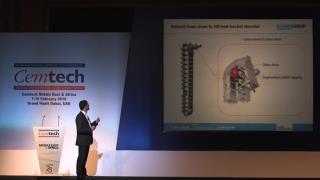
6 May 2016
6 May 2016
6 May 2016
6 May 2016
6 May 2016
6 May 2016
6 May 2016
6 May 2016
6 May 2016
6 May 2016
6 May 2016
6 May 2016
6 May 2016
6 May 2016
6 May 2016
6 May 2016
6 May 2016
6 May 2016
6 May 2016
25 April 2016
25 April 2016
11 March 2016
11 March 2016
11 March 2016
11 March 2016
11 March 2016
11 March 2016
11 March 2016
11 March 2016
11 March 2016
11 March 2016
11 March 2016
11 March 2016
11 March 2016
11 March 2016
11 March 2016
11 March 2016
11 March 2016
11 March 2016
11 March 2016
11 March 2016
21 December 2015
15 December 2015
15 December 2015
15 December 2015
15 December 2015

15 December 2015
15 December 2015
15 December 2015
15 December 2015
15 December 2015
15 December 2015
15 December 2015
15 December 2015
2 December 2015
2 December 2015
2 December 2015
2 December 2015
2 December 2015
2 December 2015
2 December 2015
2 December 2015
2 December 2015
2 December 2015
2 December 2015
2 December 2015
21 August 2015
21 August 2015
21 August 2015
21 August 2015
21 August 2015
21 August 2015
21 August 2015
21 August 2015
21 August 2015
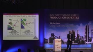
21 August 2015
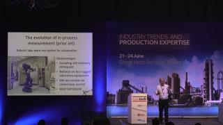
21 August 2015
21 August 2015
21 August 2015
21 August 2015
21 August 2015
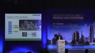
21 August 2015
21 August 2015
21 August 2015
21 August 2015

21 August 2015
20 August 2015
20 August 2015
18 August 2015
18 August 2015
18 August 2015
18 August 2015

30 June 2015
29 June 2015
29 June 2015
29 June 2015
29 June 2015
29 June 2015
29 June 2015
29 June 2015
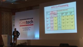
29 June 2015
29 June 2015
29 June 2015
4 June 2015
4 June 2015
2 June 2015
2 June 2015
2 June 2015
2 June 2015
29 May 2015
29 May 2015
28 May 2015
28 May 2015
28 May 2015
18 February 2015
17 February 2015
13 February 2015
13 February 2015
Try searching for another title.