
2 September 2026
This transcript was generated automatically and may contain errors.
Hello, and welcome to Eck Live, our first webinar of the year. welcome back. I hope you've all had a good break and New Year's celebrations. my name's Tom Armstrong, managing Editor of International Cement Review. and it's great to be here for this webinar on carbon capture for cement plants. we've got around 1200 of you registered and over 120 countries represented. So I think that underlines what an important topic we have to discuss today. So a brief word about our 2024 live webinar series.
like the previous years, we'll be covering all topics throughout the manufacturing process a full year of webinars, and most of them taking on place on the first Wednesday of each year or each month rather. we'll be showcasing the latest advances from across our industry and the best examples of manufacturing and excellence in cement production. many of you know our magazine, if not here it is, international Cement Review. take a look go online, explore covering the whole of the cement industry manufacturing markets innovations. a few other publications that come with our subscription. And just out now is the Global Cement Report. do take a look.
It's a fabulous piece of work covering a hundred and 70 odd countries. statistics production consumption, import export really a treasure trove. Everything you need to know about your industry. the latest position out now and online. so coming up soon, we'll be live in Dubai for decarbonizing cement, our conference each year in the Middle East. a really great program lined up. please do take a a moment to, to, to look at the program, the speakers and if possible get yourself out to Dubai in February. a wonderful way to start the year and really plug into industry and developments now, but now to get on with our webinar for today. it's a really interesting topic. It's a new topic.
It's one that's gonna transform our industry. we've committed collectively. The industry's committed to net zero carbon emissions by 2050 in the short term that will be taken care of by deploying the traditional, the proven technologies, alternative fuels, clinical reduction upgrading assets energy efficiency and so on. But that still remains 40% or so process emissions that will need to be captured and dealt with if we're gonna reach net zero. and unavoidably, this is going to require carbon capture technology a technology that is maturing, it's evolving. there are multiple forms of carbon capture at different levels of readiness. and there are different costs associated.
there's a lot of uncertainty, and this webinar seeks to explore some of those new solutions. and, and hopefully just start bringing light to an area that's gonna require massive investment going forward. we won't be talking about utilization or storage of carbon, which is a an incredibly important area, but beyond the scope of this webinar. So really pleased that we can introduce this topic with some excellent speakers. we're gonna look at specific solutions, calcium looping fu absorption technology. We're gonna look at project delivery and the role of digitalization and energy management. we'll hopefully give you a good overview, but some specific solutions also explored in detail.
Here's the agenda. and to kick us off today, pardon me, I'm very happy to welcome Mattis Mesman who's gonna talk about primarily Oxford Fuel but also more broadly about carbon capture. Mathias, if you'd like to start sharing now while I make your introduction many of you will know him from previous emtex, but Mattias is the chief technology officer at KHD with a very deep knowledge of the whole cement production process. he has a master's degree in mechanical engineering and process engineering. he joined PhD in 1995 holding roles of process engineer, director of research and development and vice president of technology and r and d.
He then joined Lusia in 2011 as technical director and was also the founder and managing director of exergy. He's now chief technical officer at KHD with more than 25 years experience in international industrial engineering, and is a recognized expert in the cement and mining industries. Perfect. to get us off for 2024. great to welcome. Mathias, please go ahead. Alright, thank you very much for the introduction, Thomas. That was already setting the frame quite nicely about the subject of today. Welcome also from my side, everybody.
I have the pleasure to be part of this webinar today, and I'd like to give you sort of like an overview a presentation on carbon captured technologies for the cement industry. and I'd like to I'd like to switch my, my presentation to this one, so I'll be ready to change the slides. Alright, so carbon capture on this cement industry. I mean, this, this subject is wandering around and everybody's talking about it. And the elephants in the rooms, of course, are, why do we have to do it? How can we do it? And what are the challenges and possibly also the solutions. And I'll try to give answers to those important questions during my next 20 minute presentation.
why carbon capture for the cement industry? What I show you here is a diagram of the scenario calculations of the change in the global mean surface temperature of the world depending on how we now drive forward the decarbonization of our industry and our lives. And what you see basically here is different scenarios of, of the intensity of decarbonization we're utilizing as mankind. And what you see here is basically only one scenario. The yellow one is keeping the world average temperature below two degrees. And this is the only one where the temperature is not running off in an, in irreversible ever heating up scenario.
So if we want to keep the ecosystem of the earth under control without having the temperature running off, we have to keep and realize the two scenario, two degree scenario or maximum 2.3 scenario. and that is quite a challenge, as we all know, obviously. so we are all in, in this and have to pursue the target of keeping the temperature raised below two degrees. Now, the next question that is dealing that is being dealt with in our industry and the whole lot of criticism coming to the cement industry being responsible for 8% of the global manmade CO2 emission. we'd have to realize that cement and concrete are basically the most eco-friendly building materials we're having.
So all that criticism that's coming towards the cement and concrete industry is coming up because cement and concrete is the most used element element product on earth. all the other alternatives that are being proposed like using timber, wood, or glass or steel or plastics or aluminum or other building materials, they all have a higher embodied carbon, and they all have an a higher embodied energy. So we see that concrete and cement are the two building materials which are most eco-friendly in terms of CO2 footprint and embodiment. And in terms of embodied energy.
So that is good news for the cement industry because it says that because of the size and the magnitude of cement and concrete that is going to be needed, concrete and cement is still the most eco-friendly and specifically the most CO2 friendly building material we're having. So there is no future without cement. That is for sure people can discuss how much cement is going to be produced, and we we're going to see later down the line, but there is no future without cement, but cement has to decarbonize. This is the essence of the two slides I have been showing so far. And we all know that there are lots of ways to reduce our carbon footprint.
And this diagram taken from the VDZ roadmap shows that on our way from today towards decarbonization, we can utilize a lot of carbon redu reducing steps in various steps along the value chain and clinker production, cement production, and, and all these kind of things. But in the end, what remains to be done is to still capture what is left over as unavoidable CO2 emissions. And that's why we need to capture carbon in the cement industry. And that's the setting the scene of, of the webinar today. So how can we do carbon capture in the cement industry? I've put together here what I believe to be the four most important aspects about capture technologies in cement.
First of all, there are these technologies themselves and we are talking about the whole range of physical and chemical and biological processes and procedures and phenomena, which we can make use of the most well developed and, and known one, of course, is dealing with absorption. but we're also having absorption processes available. We have available everything that deals with face, face change, and that deals with variation of temperature and pressure. we have available for separation membrane technology and membrane assisted separation technologies. And we have available the whole realm of, of bio fixation like for example algae growth.
So these are technologies spanning the whole range of, of physical, chemical, and biological processes. Then the question is, what is the best of those to use? And this answer cannot be given easily because every site every cement plant that needs to be decarbonized has different set of influencing parameters. For example, the size of the equipment is important. CapEx of course is important, but also opex is important. providing these pressure and temperature differentials will cost effort. the consumables will cost the quality of the required product is important to know. I will come to that later on. the transport properties of the captured product are site specific.
also to some extent, the applicability as such, will be not universally identical for every case. And efficiency will also play a role. And when it comes to investment safeguarding, there are also some aspects to be, to be looked at. as we know, lots of these technologies, which I mentioned here, or which are spanned up by, by this list here come with different technology readiness levels. and, and actually there's only one absorption technology that is technologically ready at level eight which is almost industrially proven. and all the others, they are in some development phase and need to be developed towards industrial applicability.
So it's an ongoing development, which we'll be looking at over the span of the next 20, 25 years. And one very important aspect is the usage and commercialization of the captured carbon, because nobody will spend millions of CapEx to capture carbon if he doesn't know what to do with the capture carbon in the end. will it be stored or will it be utilized, or what are the logistic options to get it from A to B in order to have it stored or utilized? So this slide shows some of the capture technologies. I've taken it from a work that has been published in the Journal of Carbon two years I should say three years ago.
And it shows quite nicely the range of physical, chemical and, and biological phenomena, which we can utilize in order to capture carbon. And as I said what is known today at, at, at sufficient readiness level is only the upper one, which is a chemical absorption pathway like Mia and, and, and other amine scrubbing lo liquids, which are being used. But as you see here, there's a whole lot of other physical and chemical processes, which we can use. And, and I, I guess we are gonna hear more about that within this webinar from my fellow presenters in, in the following.
So we talk about absorption, absorption, calcium looping, cryogenic processes, membrane processes with all their sub-processes and, and variations coming in second level and third level. Now, as I said before, once we capture the carbon, what are we going to do with it? and this diagram has been taken from my, my colleague Una Kato from VTT. she published that in her master thesis one year one and a half years ago. And it shows that, again we can utilize a lot of pathways to use the capture CO2, for example, we can mineralize aggregates and concrete and, and, and other mineral components to store the CO2 into the minerals.
But we can also chemically convert it into a whole range of chemical products. and if you talk to the chemical industry, they have the same challenge from the other side because they have to de fossilize by 2050. They should not use any more fossil carbon to produce their products. So on, on a top level view on management view you could say it's very simple. Take the carbon dioxide from cement plants and give it to the chemical plants. And they, they produce their products with the carbon dioxide from the se from the cement industry. And I still believe that is a huge part of the future.
But the, the way to get there is complicated in terms of technical things, in terms of business model things, in terms of logistics and everything. We can also use biological conversion, as I said before, LG growth is, is an example for that. other direct uses in refrigerants or in the food and beverage industries, industrial gases, enhanced oil recovery lots of direct uses and of course, pipeline to storage. Now, if we take a cement plant and want to capture the carbon a regular cement plant with a CO2 content in the of gas below 30%, maybe sometimes 20%, and we want to transform it into into a pipeline or utilization pathway, then we have to understand, we first have to process the of gas.
We have to dut it, we have to dry it, we have to cool it. we have to ox the, and we also have to get out the volatile organic components. only then we can apply one of the capture technologies. And the capture technologies usually don't give you the quality you need, so you have to purify it afterwards as well, before you can pressurize it and then put it into a pipeline or into transportation or whatever you do with it. So there, there's a considerable technological effort we have to spend. Now, what we know meanwhile, is that if we concentrate the CO2 in the off-gas of the cement plant the cost for this transformation is much less.
and specifically the cost for the capture and the purification is much less depending on what kind of capture process you put here you may not spend identically much effort for, for these gas preparation steps, because the capture processes, they are different in their sensitivity to these pollutants, which you try to take out here. So that is what we know. If we concentrate the CO2 in the of gas, then the cost for the capture and, and the pre-processing steps for the capture are much lower. So what are the CO2 concentration technologies for cement kils? first of all, and I think the, the best known is the oxy fuel process. we have two, or we, we have different kinds of oxy fuel processes.
Maybe at this time I should say that oxy fuel is not one single process with a flow sheet calved in marble. but it's more a concept and it can be materialized in different ways. the next one probably most of us know is the, so-called lilac process, or indirectly heated calcination. then we have calcium looping as a technology for CO2 concentration. And something that may be a little bit an outlook into the future is electrification easy to understand. If we bring in the heat for the process, not by combusting fuels, but by electric energy, then we don't have the the flu gas of the combustion. And what we get out of a se cement plant is almost a pure CO2 strain with a little bit water.
But automatically we, we can spare a lot of effort for this flu gas preparation before we capture. So those are the technologies generally for CO2 concentration. And let me run you through a couple of examples to show you what is behind that. some people think oxy fuel is a relatively new technology. In fact, it is not. this diagram is taken from the international Energy Agency from their first roadmap published in 2008. and please don't be confused by the lots of boxes and arrows you see here. I'd like to draw your attention to mainly this set of red arrows here, which show the recirculation of the flue gas that is getting out of the pre heater and recirculated into the rotary kill.
with that we are putting oxygen into the kiln and into the precal signer from an air separation unit in this case, to provide the oxygen that is necessary to combust the carbon in the fuels, which we put into the kiln and to the precal signer. So by, by this process, we are driving out the nitrogen and replace it with circulating CO2. So this way, we are able to generate a concentration of around 75 to 85 percent of CO2 in at this position. And then we can bleed off the CO2 rich stream for CCS or CCUS. That is the basic principle of fu. if we look at how this looks in a real cement plant you, we come to this diagram, which might be more easy to understand for a cement guy. same thing here.
Please look at this arrow sequence given in black. In this case, we take the pre heater off gas. We run it in cycle. we do some things with it. we condense it we have a condenser and, and we purify it, and then we can bleed it off for for capture purification compression and whatever we do with transport storage or utilization. and the remaining stream we feed back in this case into the cooler. We mix it with an oxidizer with oxygen, in this case also from air separation. then we will be having a mix of CO2 and O2 here in the cooler. Feed it to the kiln, feed it to the catina and, and build this circle, as I've shown before.
Now at this point, again it is important to understand this is only one way to do oxy fuel. for example, here, the cooler is being run in, in two units. The after cooling zone will be operated with pure air. And this pure air will be giving is heat. well, we will run into a heat exchange and will be additionally heated up to be used in the raw mill. As for drying the raw materials there is also a possibility to run the complete cooler in fu mode and, and, and take the heat from somewhere else to run the raw mill. Different options possible case specific optimization is necessary. Another oxy fuel way would be partial oxy fuel.
Also, this has been proposed, you see this typical recycling here in disposition, where we take the exhaust gas from only one Preeta string and we circulate it back in here. We take the off gas from another Preeta string to satisfy the demands for the raw material drying from this one pretest string only. As I said before fu is a concept rather than a fixed way of, of of, of doing it. Another option is to run oxy fuel without recirculation. This is what some people refer to as oxy fuel. Second generation. you see, there is no recirculation here, which means the cooler is supplied with pure oxygen in this case, at least in its hot zone. And then this pure oxygen is fed into the kone.
And this, the fuel is oxidized in a pure oxygen atmosphere, which will be reducing, of course, the gas flow in the system. And that would generate much smaller equipment here, which is, is probably a good idea to do. So. However, there are some technological concerns at least as I understand it. because the, the combustion in pure oxygen will have a different flame shape, flame type intensity the tightening of the cooler will be an issue. and also, I, I, I personally would have some concerns because we, we are still talking about a cement plant where everything can happen. And this, this system is very much sensitive to to false air ingress, which needs to be suppressed very much.
once you open doors here to, to clean the calina or something like that, or the cyclone, excuse me, then you will have a massive inrush of, of ambient air, which is, which is diluting the, the process gas. And it remains to be seen whether this is feasible or not, but it's also a possibility and it looks good on paper. another option for CO2 concentration is calcium looping. there's also one pilot project going on in Italy. the concept looks a little bit complicated, but it's also quite easy in the end. take a look at those two red carbonator and Calina units here.
the, the basic principle is you are running calcium in cycle here, and you use it as a regular calina here producing pre-cal meal. And you use this pre-cal signed meal on two ways. First of all, you branch off a little bit and use it as a regular raw material for the kiln, but the bigger portion is being put to the carbonator, where this CAO takes up the CO2 from the cyclones from the gases coming from the cyclones here. So this, this CAO, this decarbonation limestone takes up the carbon dioxide and then runs back in cycle into the keine. So you have many times higher material load circulating here, and you branch off a little bit and use it as raw material for the ke.
Next thing I'd like to show here briefly is this indirect heated calcination. You see here a special type of calina which consists of an inner tube and an outer tube. and you have the process the cement process, the decarbonization running in this inner tubes, and you have the heat supplied to the outer tubes. So you decouple the process emission of CO2 from the heat generated CO2 which results in a, in a pure CO2 stream, coming from, from the process, which you can capture here. But of course, this is only a partial capture.
Only what is coming from the decarbonization step in the kina from the raw material can be captured all the kiln CO2 and the fuel CO2 will probably not be ready for capture. Now, with all these different options I've tried to also give an overview on, on, on how to compare those in terms of their applicability pros and cons.
and I've taken a publication from four years back where a team of researchers have compared the regular amine scrubbing technology with oxy fuel technology, with chilled ammonia process, which is just another process utilizing a different different solution with different temperature and, and, and pressure variations membrane assisted and calcium looping, integrated and tail end, and this case. And then they have shown what is the specific energy consumption for carbon captured. So what you see here on this vertical axis is the amount of primary energy utilized or necessary to run these processes.
And you see that the, the amine scrubbing technology, which is the only one that is really ready for use today in industrial size consumes a whole lot of primary energy. and, and all those technologies have different energy consumptions. And the oxy fuel is by far the most energy efficient. Now, this shows the different state of technological readiness. we talk about, we see the typical naza driven TRL scale, which goes here from lab scale four to nth of a kind proven concept, which is industrially ready at TRL level nine. And we see that only the MEA process, the, the amine scrubbing process is ready for industrial use.
All the other ones go in different levels of prototypes, pilot scales and demonstration, and first of a kind industrial scale. And our objective will be to push all those into that direction of TRL number nine. Now, after this short overview, I'd like to just briefly, not really extensively show you how KHD can support you on your, on your way towards decarbonization. we have started an initiative under the title Cement Beyond Carbon. And I, I'd invite all of you to visit our website, k hd.com and cement beyond carbon to get more information on, on the several technologies which we are facilitating within the range of, of our competence.
we see our competence in, in that field that we provide technologies within the traditional cement plant that allow easier integration of downstream capture, easier integration of, of carbon capture and utilization and carbon reduction before capture, like energy efficiency and, and clinical reduction in cement, s scms, and all this kind of stuff. So, I'll be very brief on showing you only a few of these technologies. and I'd like to refer to our website for everybody who wants to get more information on that. First of all, fu driven by the knowledge that I've shown you just before that Oxy fuel is by far the most energy efficient way to capture carbon.
We are concentrating on developing FU technologies on r and d. We're also working on electrification and other things, but for the time being and ready for projecting ready to execute in real life projects, we have oxy fuel available in, in various ways. And what you see here is a schematic of an fu plant of, of a certain materialization way. it might be possible that in, in a specific case, we, we'll do it differently, but in this case a gen as a general generic picture, we would do it like this. You'll see the exhaust gas preparation and recirculation. We have a branch off to the carbon capture unit here, and then we recirculate into the clinker cooler and run the process like this.
the, all the arguments you can see on that list we have all the technologies developed specific oxy fuel, kiln burner is necessary specific technologies for reducing false air intrusion is necessary. specific control concept is necessary. A specific cooler concept is necessary. All that is available. Next thing, of course, everybody's mind is also Clay Cal signing. this picture shows a typical flash cal signer consisting looking like a whole lot of spaghetti, but it is not really complicated. the knowledge and the knowhow of the process is what is important here.
You need to be able to control temperatures and residence times counterflow processes and, and dusting and cyclones and flash tube technologies, color control. It should be alternative fuel ready. We have all these concepts ready. we can supply these plants in different types as flash tubes, but also as rotary kills. And why is that so important? This is so important because clay is the only raw material that is available abundantly at scale to replace limestone in cement. and that's why when fly ash and other s scms will go down in the, in the, in the way of decarbonization of our industries clay will be the alternative that is abundantly available all over the world.
Then we have our power rotta technology. Of course you see it here in green that is a very flexible combustion reactor, gasification reactor for a cement plant that can use a wide range of very big size secondary fuels to reduce preparation costs on the, on the alternative fuel side and providing excellent operation conditions without jeopardizing the clinker quality produced. We have 12 references running now, all, all of that with excellent performance.
What I should also say is that this PA rota is good for NOx reduction as well, because we can branch off from the tertiary airline here, feeds some portion into the PY rotor to provide oxygen, but we can operate this PY rotor under reducing conditions producing a lean gas, getting into the, reducing the NOx from the kiln, and then put stage air on top. So we can, we can achieve even at highest substitution rates, low co and low NOx concentration in the of gas. And finally I'd like to hint to our new product, KD promax, which is a digital twin suite for optimized production and maintenance. I'd like to invite you to see more of that in on our website.
just so far it contains basically three basic functionalities. First of all, connectivity, industrial Internet of things, asset monitoring, KPI benchmarking possible with this, either within one plant or different plants to each other. and it contains a maintain module, which has a full-blown virtual reality and augmented reality functionality, spare part integration, spare part identification, and ordering tutorials and all those things. And the produce model contains an RTO basically and other intelligence systems for machine control and optimization.
And our RTO, which is a real-time optimizer or formally talked about as expert systems contains a twin set of ki driven artificial neural net systems which which adapt themselves automatically to the present state of the operation. And all that is hedged by process knowledge and knowledge of how to operate the plant. So this is a new approach to ki based digital twin optimization of a cement plant. With that, I come to the end as I said a whole lot of things, I'm looking forward to answering some questions of yours and invite everybody to visit our website for more information. Thank you very much for your attention. Thank you very much, Mathias. Excellent presentation.
And I think you've introduced all the kind of key technologies and lots of the key points around carbon capture itself. really it's a technology that is evolving at different te technology readiness levels. the application will depend on your plant. I guess there's not one clear solution necessarily. maybe just one quick question around prices. Okay, so co cost of cost of either retrofitting or actually installing a, an fure line either a on a perton of clinker basis, or perhaps what, what is the rough range that we're looking at? or, you know, people are asking questions around, you know, what's the breakeven given you know, current CO2 costs and these kind of things.
Okay, it's a big topic, but just in a, in a short comment on how expensive is carbon capture? Yeah, you like the easy things, huh? honestly speaking, Thomas there is no straight answer to that because of various reasons. and the biggest uncertainty in answering this question about the break even is of course, the carbon cost. if the carbon cost well, I, I'm involved in, in r and d projects around oxy fuel and carbon capture since more than 12 years. when we first did, did this study with the ecra on, on carbon capture and, and oxy fuel back in 2010, we were assuming that any kind of carbon capture must or can only be viable at a carbon price above 120 Euros.
I think at that time, we said we, we are getting close to that. it's getting real. but then still there's a huge difference whether you think you'd have to build an oxy plant, oxy fuel plant new, or you retrofit an existing one. And I would guess that the, the, the, the retrofitting will be maybe in the order of magnitude of only 10% of the cost of building a new plant. but still what is important to understand also is what kind of quality you need as for your CO2 product. if you go for pipelining specification, they accept only 99.8% purity with only a minimum amount of water and no impurities at all.
in order to get there, you will be spending almost as much for the for the CO2 product, cleaning, purification processing plant, as for the cement plant. Mm-Hmm. Yeah. So that gives them a little, in a nutshell it's, it's hugely expensive. obviously will, will happen earlier in countries which have a carbon price Only, only in those countries, it, it'll be viable, but then it will be necessary. Yeah. This is how we have to see it, and there's a huge, i i, forgive me, only one sentence, maybe as a last explanation. maybe I didn't emphasize that enough in my, my presentation. It is very, very important to know upfront, what am I going to do with the CO2?
Because some utilizations, they get along without all that cost of purification, and that saves you a lot of money. And, and transportation, pipelining, barging or, or trucking is hugely expensive. So you need a regional utilization that allows to live with not a purified product that is the, the Cardinal way. Yeah, like cement itself, it's better, you know, it's, it's if it can be consumed locally you, you eliminate or reduce the, that, that transportation cost. Yes. Which is a big factor, Excuse me, for not being able to give you more precise answers. No. But that, that's part of the discussion. So that, that's great. Thank you very much. Matthias excellent presentation.
There are some questions there in the q and a. If anyone wants to ask any more, I'm sure Mathias would be typing some answers. we're gonna move straight onto our next presentation to keep the momentum going here. I'm gonna welcome Mohammed Mag Deldin and Martin Ha from Sumitomo, S-H-I-F-W Finland. they're gonna present tail end and integrated calcium looping solutions to decarbonize, clink and manufacturing. Now, Mohamed, he's spoken before. he's the director of carbon capture at Sumitomo, responsible for the strategy and global business development to the company's CCUS solutions.
He's been with Sumitomo for over three years, having a range of roles within r and d technology and product development, and he's joined by Martin Half, who is the C-C-U-S-R and D manager responsible for solution development and the management of the company's CCUS demonstration projects. I'm gonna hand it over to you now to, to get started. Welcome to you both. Thank you. Thank you very much, Thomas. I'm very happy to be here again. And first of all, I just wanna wish everybody joining the webinar, happy New Year's and grade 2024. I ahead. my name is Mohammed Mande but please call me.
I work as Director of Carbon Capture and today, actually I also would like to take, the previous speaker gave us a really good introduction into carbon capture technologies, this application, the cement industry, and really set the stage pretty well for us. Now, to give you a bit of a deeper dive into specific application, which is calcium looping and what we call at s of W as s of w Cal plus, how it can be implemented in clinical manufacturing for the purpose of carbon capture decarbonization, and, and the different added values it, it brings to existing operations.
I'm joined today by my colleague, Martin Hoff, which will he will cover more on the demonstration and development activities that are ongoing from our side. But briefly for those who of you who are not familiar with SFW where we're coming from it's an abbreviation for Heavy Industry fw. We're a global industrial OEM with over up to 1,800 employees, professionals, and experts in delivering and executing projects globally. I'm personally speaking now out of Finland but we have over 20 locations and, and, and more than 800 global references. I'll show, and I'll talk a little bit more about those later on. but just to, to, to bring a little bit into focus the technology of the day.
so car today we're talking about carbon capture, specifically calcium looping, and to be more focused, calcium looping applied within Fluidized bed. And Sumit, SHI fw our roots come from Finland, where fluid Fluidized bed technologies was originally developed piloted back in the 1980s and commercially introduced globally up to 890 of such plants. So we have knowledge of fluid ice that combustion with specifically, almost exclusively now, alternative fuels, solid biomass and waste. We also have fluidized bed solutions for gasification the production of syngas. And as, as, as mentioned the topic of the day, which is carbon capture.
maybe just to give a full round of our different solution, we also have energy storage application specifically for long duration energy storage, and it's based on liquid air. But I just welcome everybody to, to please check our website you find a lot more information on, on our different offerings. this is a, a, a picture I've mentioned earlier, a couple of our references, commercial references, because I think the previous speaker actually had a, a, an important point when it comes to technology development, which is the TRL level technology readiness level, and, and the knowledge that you can utilize from prior experience and apply it into innovative ways and in innovative configurations.
And here, specifically in fluidized bed, there's different ways to operate a fluidized bed. And my colleague Martin will, will speak about it a bit later. But just to highlight, you'll see in the figure here our commercial plants, they go between A CFB, which is circulating fluid ice bed BFB bubbling fluid ice beds, and, and quite a wide experience with, with both type of configurations at different scales, up to the largest of those that commercially delivered, which is a 300 megawatt electric plant, or around 800 megawatt thermal capacity in terms of fuel all of these plants, of course, have been de delivered commercially.
And maybe just to point out here that we have different operating models when it comes to delivering them. So in certain areas, we can act as the EPC for the delivery of the plant. Sometimes we act as equipment and technology provider, and in certain locations we also act as a licenser. so different ways to collaborate and, and, and develop the projects together. While we were working on commercial CFPs for, let's say, power generation applications at the same time we've developed them for decarbonization applications. there was mentioning earlier about oxy fuel. we also have our own solution, SFW Oxy Plus, which is oxy fuel implemented in a circulating fluid aspect.
And then you see here in the picture on the left our demonstration project in Spain fer in Spain that was commissioned back in 2010. It's a 30 megawatt thermal unit. basically the CO2 was captured from the oxy fuel plant compress liquefied and sent for permanent storage in a apple amplifi. And there's been a lot of discussions about the advantages of, of oxy fuel and we'll, we'll touch on them a little bit today as well. one question that always comes, how can you use the advantages of oxy fuel in a post combustion capture sub? And that really where calcium looping comes into play. And, and it's also a technology that we have already demonstrated for 10 years.
Now, you'll see the picture here on the right represents or showcases our demonstration unit, oh, sorry coincidentally also in Spain where C two CCFs were capturing CO2 from an existing industrial stack and, and showcased the efficient capture performance for over 90%. So, of course, as, as mentioned, every case is specific, every solution brings different added value. there's different ways to apply carbon capture. You'll notice that in all of our products there's annotation of plus. And this is really where, what we call the added value that can carbon capture, can bring to your project and your operational facility.
So, as mentioned earlier, our focus is exclusively on alternative fuels and biogenic capture of CO2, mainly to look at carbo dioxide removal. and more specifically here on, of course, utilization and circular application has wide advantages and a role in the future. but in order to address the, the global climate change challenge that we have, we see that the role of CDR carbon dioxide removals and BES essentials. So you'll see SFW Oxy plus, which is an oxy fuel power plant to decarbonize heat and power applications.
On the left, you also see on the far right SFWH PC plus, which is a liquid solvent application, where we are developing for, let's say, small and medium scale waste energy plants. But the topic of the day, the focus of the day is SFW Cloud plus, which is the solution we think brings the most added value for heavy industries, and here specifically for cement and meteorological applications. And as the name implies, it's based on calcium, a familial absorbent, but additionally, it not only captures CO2, but it also decarbonize your scope one, two emissions, and three emissions as my colleague Martin will walk you through now. So I'll move the speaking to Martin.
Alright, thank you, mark, for setting the stage. It's a, it's a pleasure now for me being here and explain a bit more about all the calcium looping technology. How does it work and how could it be integrated into cement production. this slide basically shows the, the very heart of the process which is basically a two, two reactor system. We call it carbonator cal signer showing on, on, on the left side of the slide basically, and the capture of the CO2, the removal of the CO2 from a flu gas stream is achieved by circulating calcium absorbent and thereby exposing it in a, in a continuous fashion to carbonation and calculation conditions. In that way.
You take up the CO2 on the carbonator side, forming the calcium carbonate while on the cal signer side by means of higher temperature level, basically decomposition of the calcium carbonate is happening leading to a situation that you have on the one hand relatively pure CO2 product ready for further utilization and or storage following further purification in the CPU unit. And in the other hand, you have the calcium oxide in originated form that is then basically reintroduced to close this loop. You can see on the right side of the slide the operation regime of this process in very fundamental terms, showing temperature and, and CO2 partial pressure levels of this two reactors.
you can see here that basically both reactor system operate on relatively high temperature level. We talk about 650, 900 degrees, and in especially Cal signer site, this temperature increase up to 900 decrease is achieved by the oxy fuel combustion of additional fuel. key features of that technologies are as follows, as stated earlier, it's, it's basically a multi-product technology. Naturally, the main the main job of this concept is to capture the CO2 and make it available in a highly purified form. So that is the main purpose.
Nevertheless as stated, the the temperature levels are relatively high, that leads to the specific advantage that you could very efficiently recover the heat, for instance, by the implementation of a dedicated water steam site to generate electricity. and as a, as another product available from, from this technology, of course, you get the ign limestone, the so-called purge as some kind of byproduct of that process. And this, so-called purge stream. It, it's not, it's not the waste. It basically represents a feedstock that can be used basically in, in clinker processing units. moreover, I would like to highlight few, few features.
Basically this as it is stated here, this concept is applicable to different, different industries. Initially, it has been considered to large extent for fossil based power generation, however, nowadays clearly focuses on, on more, let's call it hard to abate applications covering, for instance cement, cement processes. I would like to highlight here that the, let's say the main components that are applied to implement this process are already commercially available and demonstrated because the, the contacting of the sorbent in the form of solids and the gas, for instance, Luga in Carbonator site is done in, so-called circulating Fluidized bed systems.
And I would like to go a bit more into this into this term to opening up what, what is it, what is a CFP? What is a fluidized bed? So basically you can say it describes in a way the contacting regime between, between the solid and, and the gas phase. There are in, let's say, different, different concept concepts distinguished, distinguished according to certain characteristics, starting with, let's call it a fixed bed or moving bed on left side. if you think about that, this is quite often applied in incineration units of municipal solid waste, for instance. Then next, next stage here is so-called the BFP Fluidized Bet. Here already particles are bit smaller in size, higher gas velocities.
Nevertheless, majority of the solid inventory of such a system is still in the, in the lower part of the bottom in the, so-called dense bed one increases further gas velocities in the system. You end up what we call like a circulating fluid dust bed reactor. You see here as a distinguished feature, you have the cyclone in which basically gas phase and solid phase are separated while gas phase is released to let's say back pass each recovery section and the solid fraction is returned to the actual furnace or riser. Weather reactions are, are happen. this is now shown here for the, for the, for a combustion system.
And nevertheless, given this specific advantages of this concept of CFP and that you have a very good excellent mixing between the gas and the solid phase and a well controlled temperature profile within the furnace, this concept is, is also very, very suitable for other chemical processes. For instance, what is happening in the carbonator uptake of CO2 by solids carbonation, or like, for instance, what we are doing in the cal signer to release the CO2 again from the solid phase.
if you move forward to the next slide, some, some more specific details and, and, and, and features of this, of this CFP concept as, as stated already by Mark, I would like to highlight here that it, it is very well suited to digest a quite a wide range of different fuels talking about different types of biomass, waste derived fuels. All these kind of fuel candidates can be basically used in such a, such a installation. And as shown before earlier, the this, this concept and this yeah, suitability of, of, of c fp boilers is already well established and proven by, by a long track record of different references.
moreover, as said earlier, temperature profile is, is well maintained that lead to a situation. You have very good possibility to control the emissions that are typically formed during the combustion leading to ox level, no CO level, low CO levels, along with a high and very efficient burnout of the fuel. And you can imagine that the combustion process that is ongoing within the furnace of such a boiler is more or less like a flameless combustion. The, the actual fuel represents just a small percentage of the entire solid inventory in that system. Alright, let's move forward to the next slide. Now, having this set, you can see a more detailed view of, of typical calcium looping arrangements.
Starting from left side, you see the carbonator, typically it starts there. CO2 is emitted by a host plan. You introduce it to the carbonator in order to remove CO2 from gas phase leading to a flu gas. Very low in EC O2 content following separation of gas and solid phases in the cyclone, the loaded absorbent, largely consisting of calcium carbonate is introduced to the igner, where by the addition of fuel in oxy fuel environment, regeneration of the sorbent is carried out leading to this highly purified CO2 product at the outlet and the regenerated sorbent stream on the other hand, which is then fed back to the, to the carbonator.
So again, carbonator system, basically you have the reaction between the calcium oxide, the CO2, no combustion, while on the Cals side you have the decomposition of the load absorbent and basically the combustion of the fuel. Just to highlight here the stated earlier potential revenue stream, you could expect from such a system, it's not only limited to doing the job of the capture. Moreover, you could generate revenues from additional power that is generated and or restricted talk about carbon dioxide removal credits, depending on the fuel, depending on the nature of the carbon that you are capturing.
And moreover, also nitrogen or hydrogen as a byproduct depending what source of oxygen supply is in focus. Alright, this very basic concept has been demonstrated in, in, in several test units worldwide. Would like to highlight here just one of the most relevant ones located in Spain. As said earlier, we are talking here about the two megabyte scale installation with more than 10 years of extensive testing of this technology. Okay, so now I would like to go to the different options that we are considering for, for cement industry. Distinguishing here between the, so-called tail end solution and the integrated solution. This slide shows in a very simplified fashion how this could be done.
So the tail end solution basically represents easy to retrofit concept. Basically you take the flu as from, from the, yeah, basically point of extraction from, from the salmon plant. Eventually after, after the raw mill or after the pre-heating system, depending on the, on the installation, you capture the CO2 by using the limestone, which is typically available on site leading to a stream of CO2 available for utilization and or storage. And the CO2 depleted flu gas perch potentially could be used in the clinker manufacturing process. and thereby reducing the amount of limestone that is, that is required to produce the product.
On the other hand, the integrated solution, as the name suggests, it's highly integrated within the existing line. And in that sense, basically the cal signer that you have in the calcium rooting system and the cal signer that you have in your clinical manufacturing process are basically one unit. In that sense. Of course, a more efficient heat utilization is, is possible between calcium looping system and, and integrated system. Again, this solution makes use of the fact that you basically use as a sorbent limestone, which is available on the site. alright, these are the two different concepts that we are currently developing.
I would just shortly highlight the two development projects we are currently in. You can check later on from internet more details about this, about this project. Martin can you, you, you've muted yourself. Can you unmute And Okay, we're back. Now I need to apologize. It seems we have some technical problem here. I will just reshare the presentation. I hope you can hear me still. Yeah, We can hear you. Yeah, that's a good idea. If you just re-share, then we should be able to restart. So I am going to share now again, the presentation, apologies for this share screen. Okay. Okay. So I hope we are now back on board. Yeah, almost can see. Yeah, we can see in here. Everything. Okay. Apologies.
So let me just jump to the slide where I stopped. okay. Yeah. So again, you could, you could check from, from the homepages what what we are doing in this, in these projects together with, with the partners. I won't go more into the details at this moment and having this set, I would like just to shortly return the ball too, too marked for the final remarks on this topic. Yep. Apologies everyone for the, this, this technical challenges. But yeah, thanks. Thanks Martin. just to follow up of course along with our, our development activities we, we have a commercialization roadmap for, for calcium looping.
and, and here this is a case that we looked at where feasibility study was conducted for a commercial scale plant. this is specifically for a tail end application of, of calcium looping, capturing up to 400,000 ton of CO2 per annum from the clinker process in a, in a sense as, as, as highlighted earlier, we're looking at the utilizing RDF in, in, in the calcium looping system or al alternative fuels. you see some numbers giving more or less generalized performance of, of the system. What is key to, to, to highlight, of course, is the carbon reduction potential of the solution.
So you see the overall performance of a combined cement plant and a calcium looping as a tail end led to negative carbon of around 178,000 ton per annum. And this is scope one emissions reduction from the stack. But you also see there is a reduction of scope two emissions, which is the indirect grid associated CO2 of are up to 77,000 tons per annum. those avoided the CO2 from electricity. That's as a result of a net power production from the calcium looping in, in such scale at 28 megawatts.
and it's important to highlight that that covers not only the consumption of power for the purpose of carbon capture, that also covers the existing cement plants, power consumption, and leads also to additional or excess power to be sold to the grid. as firm decarbonized electricity. And, and as Martin highlighted earlier for such a plant, you have the opportunity to produce decarbonized calcium oxide and here around 80,000 ton per annum. those of course can be redirected back to the clinker process, reducing your own consumption or direct consumption there of limestone, and as a result, reducing your emissions from the clinker process or can be applied as additional capacity in your plant.
And if we go to the next slide, of course, when we looked at the solution and applying it, we also run a financial feasibility of the impact of the solution on the operation. And you'll see on the left side the cost of capture of CO2 and it was around 50 euros per ton. I will not go into too much details on the assumptions, but most of which are listed here. and, and just to highlight that 50 euro per ton of CO2 captured looked only at the opportunity to monetize power as a byproduct. But as mentioned earlier, there additional revenue streams that can be stacked.
but this case only, we looked at power and, and of course, as the full solution we considered in this scenario transport and storage, which led to a cost and most importantly remaining to be below ETS pricing that we see today and, and projected for the future. So just to conclude from our side so SFW Cal plus as a carbon capture solution for heavy industry, specifically the cement industry, it's a multi-product solution. So it's an attempt also to, as, as mentioned, to look at carbon capture beyond the value of, of capturing CO2 only, and see what additional revenue streams that can support the business case can be generated. we've talked about the two different configuration.
each has its positive or added value that brings to, to, to the project. So for example, if we look at the tail end this is more on maximizing these byproducts and, and, and, and revenue such as calci and lime heat and power waste gate fees in certain locations, et cetera. but if we look at the integrated configuration, which we're currently developing as the name implies, it looks at recovering most of the heat from the calcium looping system into the clinical manufacturing step itself. nonetheless, with both configurations calcium looping and SOW Cal plus does offer a sense of flexibility and also a resource efficient way to decarbonize your operations by 2030.
that kind of gives the commercial roadmap that we have for our solution. So thank you very much. and, and again, apologies for the technical mishap in, in between. Thank you very much. Mohammed and Martin for that presentation. really interesting. Another solution variation on calcium looping. again I mean cost-wise, you, you set out some, some estimates there. so we're, we're looking at between sort of 75 and 120 euros per ton of COU captured factoring in transport and storage. Is that, is that correct? yeah, I can take that one.
yeah, Martin, if you go back to that previous slide so of course as what we are trying to highlight here, and you can see in this specific figure, and I think also the previous speaker showed with calcium looping, you have this negative cost bars, these additional revenues that, that offset your cost. So you see here at below the zero mark, then that's the revenues from power. as mentioned, there are other revenues that can be generated. Those did not become really project and, and, and site specific. So that can drive the cost of capture including transfer and storage to even lower than the 97. And this is for this specific case, we only looked at power.
but yeah, as mentioned, it can go lower. So I, I, I wouldn't lock it within a specific range within yeah, X to Y. it's, it's, it's always good that we look within a feasibility on a specific site and see how, how much we can yeah, bring this value and, and, and bring the cost of capture down. Yeah. And in terms of the actual CapEx for the installation itself, the fluid eyes bed, mm-Hmm. What kind of, can you give a kind of ballpark figure, and I guess there's integrated and, and standalone retrofit systems, but what are we looking at in terms of investment?
I think that the bar here as, as the blue part that covers cap, so they can give you an idea, but it's to highlight that of course this one includes not just the fluidized bed system, that it would include also the power generation, and it includes the air separation unit to produce the oxygen and the compression liquid effects. So the fluidized bed is, is, is a component within, within, within the overall solution. and yeah, of course then it becomes very specific on, on the fuels being fuel mix that is being applied the capacity of the plant and, and so on, that, that also has, has, has an impact on the cap up state. Very good. Well, thank you very much both of you for that presentation.
We'll we'll move on now so that we can keep to our time. But thank you those slides will be sent out after the session after the webinar ends. so really please now to be able to welcome our next speaker Greg Ross from KCA capture in Australia. welcome. Greg has over 38 5 years experience in executive roles in engineering, manufacturing and product development. He spent the last 20 years in the management of large engineering and fabrication ENG enterprises, focusing on the design and manufacture of cryogenic storage vessels and equipment and gas processing packages, as well as subsea oil and gas production technology.
More recently, he was country manager for ACA Solutions in Australia for joining KC eight capture technology, where he is now taking the company through the full commercialization of the, you know, mark three capture technology, which you're gonna hear for about now. over to you Greg. please load up your slides and, and go ahead. We can see them there. That's perfect. Alright, look, thank you, Thomas, and, and look, it, it's a pleasure to be here and, and thank you to all the people tuned into the webinar and, and also the previous speakers excellent presentations. And I have had the pleasure of speaking with Matthias in, in a previous conference.
And it's always great to get his insights into the overall world of capture for, for the cement industry, I guess. our company is much smaller than than the speakers in, in the webinar today. So we are, we're an emerging company. we're only just starting that commercial pathway but we have some interesting technology and I, I hope to be able to share some insights with you today on both the, the company itself and and the technology that we have. KC eight capture technologies is a process licensing company that's we will, we will license our technology to the end user. We will work with the owner's engineering company to provide that process and to optimize it with their solution.
we are not a plant builder. our expertise is in the process itself and, and the integration of that process into the existing plant where we can try and maximize energy recovery in the process. So I, we believe that by focusing on the, the capture process and, and working with others in the delivery chain, that, you know, we, we will give a, it'll be a better cost effective outcome for, for the client. At the end of the day. Our company has just over 20 employees. as Thomas mentioned, we are, we are located in Australia. We are, we're just starting up in the us as we speak. and so we, we are expanding on the back of of two commercial demonstration projects.
And I'll, I'll give you some details of those in the in the coming slide. So our technology has come from concepts that were originally developed in Australia by what was called the CO2 CRC, and it was supported by the C-S-I-R-O and Melbourne University, our organization and our founder took that further and brought it up to a, a pilot stage. and now we are taking it that next stage into the commercial demonstration projects. But what we've developed over that time is a combination of, of not only a proprietary solvent which we have, but also an absorber tower, which is the major component in carbon capture process invariably ends up being the absorber tower that you have to deal with.
And we also have some fairly complex heat integration processes that we utilize to also achieve what we believe is the lowest cost we can get for this type of capture process. it's also quite a robust process. It was always designed to be large scale. originally it was developed for coal fired power stations. so right from its inception, it was always made for major capture processes. So scalability was built into it and and the robust and the ability to handle high volume was built into the process at the same time. So really what that meant is that this technology is made for those hard to abate industries. So it's cement, steel, chemical, and power.
They're the areas that we are focusing on. And, and I guess as the other speakers have, have mentioned, carbon capture is, is something that will make up 40% of the, of the hard to abate sector. and that's even after all the other applications of, of energy replacement, process replacement, all of those things have employed. So really what we are aiming for is to be part of that 40% sector that will keep the carbon capture meeting the 2050 targets. I think Mattias first presentation really laid out as he said, that there are a significant number of technologies emerging in the carbon capture market.
All of these technologies have a place and they have a purpose, and they have probably more applications better suited to them than others. and, and we are no different to that. You know, our, our process is a solvent based process, and it's made for high oxygen flue gas content, primarily focused on post combustion capture. So this is where it starts to fit well within the certain elements of, of the cement and, and the kiln industries. You can see from, from the presentation here. we are, we are sitting at a, at TRL level six, so we've completed pilot testing. We've done over four and a half thousand hours of operation on the league night, coal fuel.
we had the, the data for a, you know, a, a one ton per day capture process, but this year we will implement two commercial scaled facilities that will take us into that TRL seven range, and then we'll be able to push into TRL level eight. next year, our focus has been on two primary industries. One is the cement industry and one is in power. And I'll explain how our two commercial demonstrations fit within those in those models. But it's important to understand that this next generation of, of capture technologies, whether it's ours or others that are emerging, are all targeting this nominal figure of, of less than 40 US dollars per ton of CO2 equivalent. So that's a nominal number.
It's not industry specific. It's meant to be a guide, and it's a way of gauging how people's performance goes. In our case, we are operating somewhere around 35 to 40 on a nominal capture basis, but I'll give you some more details on how we see this integrating for simple integration into kiln applications, and then how that may be developed further into into a full integrated cement facility. So the technology that we developed started out with, with three core principles or pillars of, of design that we had to meet. We had to be sustainable, it had to be affordable, and it had to have an impact.
So the technology that we have is we believe a sustainable solution in that it will capture 90 to 95% of the carbon dioxide in the flue gas emissions post combustion capture, but also in, including in that is the fact that our solvent that we use is primarily sourced out of the fertilizer chain. So we are looking at a potassium carbonate based solvent. So that means that we are not creating further chemicals to capture CO2. So we, we've got a, a very small CO2 carbon intensity value for our actual process. The other part of this from a sustainability point of view is that our technology, our solvent is safe. It's naturally occurring.
It doesn't have an impact on the environment, which means that it can be retrofitted into systems where you may have built up areas around it, or you may have other factors which have environmental impact. So we, we don't actually have an off gas from our absorber, that's anything other than the flue gas without the CO2, some moisture, which is just water. That's part of the process. And potentially there may be some potassium carbonate carryover. The affordability part of the equation is, is built around the way we operate the solvent.
So we have a, a promoter that's proprietary in this process, which allows the potassium carbonate to work at extremely fast rates faster than the original amine type technologies. And it has the, the ability to operate within an oxygen environment. So what we can do is drive the process to have a very, very high CO2 uptake, and that means lower capital cost. It means that the pumps, the piping, the heat exchanges, all the equipment in the circuit is much smaller than you would normally see with a chemical-based solvent capture process.
We also, as part of that, hold the intellectual property for a particular design and application for the absorber, which allows us to manufacture that out of concrete so we can slip form the absorption column rather than use expensive stainless steels. and that also means that it's cheap and fast to build. So that's another part of the the system that, that we've developed. The way we load and, and, and operate the re boiler and the circuits means that we have a very low operating cost. It's up to 15% lower than the current standard amine processes. we have a standard re boiler.
Our circuit that we run is very simple, but it's the way we load the solvent with a high volume of CO2 that keeps all the costs lower. So all of these things all go to the bottom line to build a a lower cost solvent process that can be retrofitted into existing large scale plants. And that brings us to the, to the final pillar, which was the impact side. The whole technology is, is been developed really to be used in capture processes that are at the a hundred thousand to a million ton per annum and above type applications.
So we, we are not, we are not bound by scalability the way we've developed the solution and the solvent process and the absorber means that we can have a single point of capture with multiple inputs, and we can have a single point of regeneration, which allows you then to have a common output of CO2 from the system. So you're not looking to have multiple trains in operation to do the job. We can do that with one absorber system. So that means it also is very good for retrofitting to existing plants, although it can be built into into new bills for the process itself. as I said, it's, it's a potassium carbonate process, which is not new.
I think, you know, there's, there's certainly been hot potassium carbonate, CO2 and sulfur removal and natural gas been used since the the fifties. we took that process and with the inorganic promoter that we have that maintains the, the low volatility and, and low environmental impact, we are able to actually have a, a low energy of regeneration and obviously an overall operating cost in the process because the process is fully reversible and it's a known process. We're not creating a new chemical to try and absorb CO2. We actually know what the energy values are, and we also know what the output product is. So the output from the stripper has very little intrained impurities.
there will be some, some volatiles that'll have to be removed, but our system actually handles all of the other issues that you would normally have as a pretreatment section within a, a capture process. So rather than dehydrating the flu gas or drying it before we, we actually keep it saturated. So we, we want the fluid to go into the absorber saturated. So to that end, we have a direct contact cooler, which we use a slipstream of solvent that actually cools the liquid down to round about 80 degrees. And that's what flows into our atmospheric absorber. Because the process is exothermic, we actually have fluidized beds where we take energy out of the system to keep that temperature low.
So we keep the absorber running at 80 degrees. So the actual outlet stream from the flue gas stack will be 80 degrees by the time we finish in doing so, what that does, it allows us to load the solvent, and that's really where we start to see the, the real cost savings and the benefits in using the potassium carbonate based systems. So the fluid itself, what we can see here is on the right hand side of the screen is a, a lean solvent. So that is a mixture of potassium carbonate promoter at a, at about one in a thousand ratio. And and water. That's really what the solvent becomes. Very simple, very low cost.
in, in process, what you see on the left-hand side is the rich solvent that comes off the bottom of the absorber column. What we've done with the fluid is by keeping the temperature low, and by operating it in in a flooded state, we have allowed the system to actually precipitate out potassium bicarbonate. So the white solid that you see there is, is fine crystals of potassium bicarbonate. So that bottle there is holding 40% by weight CO2. So that solution sit considered atmospheric. It doesn't off gas, it fluid ices quite quickly. But what it means is that we can run the system with very, very high loadings of CO2 in the solvent.
And that's what keeps the, the piping small, the pumps small, the heat exchanges low, and that's what keeps the cost down. The system that we've designed where you were using the older high temperature system, which was designed to stop precipitating the, the potassium bicarbonate, we've taken it the other way. So we were, we've designed the process to run with the slurry. So we use slurry pumps that are readily available in the industry. There's nothing special about them, but they handle this, this fluid quite well. There's heat exchanges available commercially that handle solids, that handle this slurry quite well.
And as soon as we pressurize it to go into the re boiler, and we add heat through the cross exchanges, the solids dissolve and the re boiler handles what is effectively a highly saturated clear fluid that we then can put through the re boiler and remove the CO2 and the water. The water is returned to the circuit or it could be surplus in a lot of cases. We actually make water out of the process. We get distill, distill water out of the system, and then that CO2 stream is then passed onto dehydration and compression. In the testing that we've done so far, we end up with oxygen levels in the, in the CO2 output in the a hundred, between a hundred and a thousand PM range.
and we have no impurities, so we can actually compress and inject within normal scale, particularly in the us standards. So what we have here is, is the demonstration unit that's one of the demonstration units that's being built. But I guess just before we get into the testing and the the work that we are doing in the two test sites, just to, to, I guess, reiterate what we believe the solvent is capable of doing, you know, we, we have a 90 to 95% capture rate with low operating energy. That's what's been run in the pilot test unit that ran with coal-based flu gas. And we proved that that operated for four and a half thousand hours.
We know the solvent is safe easy to use, it's not harmful to the environment. we know that it has very little impurities and, and it's easy to to use with just normal PPE on site. So you're not looking at having special chemical handling equipment, and importantly, you're not actually looking at having spent solvent, which you have to remove from site and have that paid for as an industrial waste. the solvent losses that we do have are just carry over from the the process in the absorber. So very, very low in the, the grams per ton range. We don't have an issue dealing with socks and NOx because carbonate potassium carbonate will handle those components.
and if they're in large quantities in the flue gas, then we will remove them as potassium nitrate and a potassium sulfate, and they can be then returned to the the phosphate the fertilizer industry and actually recover some value from them. We have low low degradation because we have a high oxygen tolerance, so ideally suited to post combustion type applications. So getting onto the, where we're up to with with the technology we have two commercial demonstration projects that are currently underway. So the first one in Australia is being supported by Cement Australia, which is a joint venture between Whole Seam and Heidelberg Cement. They have two integrated cement plants in Australia.
We are lucky enough to be testing at one in Queensland location called Gladstone in Queensland, a large industrial area on the East Coast. This this unit is also supported by a group called Letter Low Emission Technology Australia, and they're providing funding for us to complete this work. So with those two supporters we are currently building a 12 million Australian dollar, which are 8 million US dollar pilot plant, which will be installed in August this year. So engineering is complete. We are procuring all of the items at the moment, and that will be assembled and installed taking a slipstream of flue gas off the just after the bag house, before it enters the stack.
So this will be a, a trial. It's it's not a, we're not producing commercial quantity of CO2. This will produce around 15 to 20 tons per day as a demonstration. So we will test monitor, we will get the performance of the unit, it run for 12 months as a minimum, and we will be able to confirm the operational costs of the unit and the longevity of the solvent and test for any impurities that may build up over time at the backend of the, of the, the kiln. In this particular application, we are just dealing with the clinker kiln, the output from the clinker kiln. We're not integrating into the whole cement plant. It's a test for, for doing that that CC O2 recovery.
and this particular one is coal fired. So we'll be dealing with CO2 concentrations in the flu gas of around about 15 to 18%, depending on which way they're operating the plant. So that's, that's our first demonstration. So it, it's for 15 to 18% CO2 in the flu gas, and it's coal fired. An example of how that would look going forward in, in a commercial sense. And, and again, this is talking about some of the, the costs that we've spoken about and some of the other presenters have spoken about. We've looked at taking a similar application for this in a a site in North America.
Now, this is a lime kiln, so obviously different from the integrated cement plant, but this is a, a preheated rotary kiln standard design that you would see in, in most of these locations, running around about a thousand tons per day per kiln with an outlet temperature of around 280 degrees C. So we've done some pre-feed work and are now looking to move into a feed study to develop this further. But this would be a flu gas capture process of around about 90%, so somewhere between 90 and 95% of the CO2 and the flu gas with a 40% turn down. Now, this particular unit runs on either coal, pulverized coal, or natural gas.
So we will have operating details from our, our pace of project in Queensland. And really what we're looking at here is everyone wants to know, you know, what's the value? Well, the CapEx value for something that's going to be capturing around about 2,200 tons per day of CO2 with an additional 250 tons per day from an auxiliary boiler that we need for steam, we'll be around about 180 million US dollars. So the opex for that runs at around about 25 million US dollars per, per year with a minimum life of 20 years.
So to, I guess to put that into context for what this looks like, this would be an integrated system that would utilize our concrete absorber with the stripper in the center and the absorber around the outside. It would be built on site it would operate right next to the two kilns. And it would take the flue gas from both kilns and, and treat it, and then return it to the stack. So this, this would be a simple integrated process, but the value we have incorporates compression and dehydration with an output gas quantity or quality suitable for onsite sequestration. So the value that we are looking at currently is around about 60 US dollars per ton at the wellhead for injection.
That doesn't cover all the sequestration costs that exist with monitoring and managing a sequestration well, and the work that's required to maintain that well over the life of the of the injection period. But it gives you an idea of of how far that we've taken that type of integration work and how far we are looking at developing that work this year. On top of this, we're working with another cement manufacturer globally, but in, in the us and they'll be looking at a a study which will be actually for a hundred ton per day small scale commercial operation in one of the US operations that will go into feed in March.
And we'll reach an FID point in November, December this year with a view to actually building the next scaled up version after what we've done in in Gladstone. And finally, just to I guess to give the, the other part of the equation that we are working on, we are also building a second plant in the United States at the moment. that plant is supported by the US Department of Energy. again, it's around about an eight, eight and a half million dollar packaged unit. It will be installed at the National Carbon Capture Center in Alabama. It will also run for 12 months.
this one, the difference between this one and the Gladstone plant is that this will be fired with natural gas, flue gas, and it will capture on four to 5% CO2 in the flue gas. So at the end of this process, midway through through next year or first quarter of next year, we will have results from two operating commercial plants pilot plants, one being at four to 5% CO2 in the flue gas, one being at 1815 to 18%, and one being on natural gas fuel and the other being on coal fuel.
So we believe that will give us a a very good broad basis to be able to then estimate alternate fuel mixes and ultimate alternate CO2 concentrations in the flue gas to be able to scale and, and design these plants for integration into existing facilities with the cement plant going into a hundred ton per day as the follow on project. This plant also has a follow on phase three, which will go into a 500 to 1500 ton per day operation. But this one would be on the backend of a, a gas turbine. So it's for the power industry in particular. So that, that's really the update or, or, or the information of where KC eight is, is up to, as I say, we're a small organization.
We are developing these two commercial projects to demonstrate the technology and provide the information to start that integration process. We haven't really got yet into a full integration into a cement facility, but that will start this year with the support of the various companies we work in the US and and also with Cement Australia with the test unit in Gladstone. So with that, that's really what I'd like to like to finish with and certainly would be happy to yeah, to answer any questions that are raised on the, on the webinar.
And if you're certainly have any interest or want to find out more about us, please look at our website KC eight capture.com or contact me and we can provide some further information. Greg, thank you very much. really fascinating presentation there. and it's great to see a project about to go into demonstration phase and which will give us so much more information and understanding about what the technology can, can do. where's the, where, where's the technology originate originated from? I know it's been applied to the coal industry, but It's, it's originated from Australia. It was developed originally the CO2 CRC development was focused on capture from coal.
and we took up that technology and, and developed it further into a more commercial package. But it's a, it's an Australian development that has been yeah, been, been sort of taken up by Casey Ape. Yeah. And the so you've got this alliance with cement Australia and then in the US it's it, it, the, the facility in Alabama, I believe is, is testing multiple types of carbon capture alongside each other. That's, is that right? And that's correct. One, one of the number that will be under evaluation. It is, yes, there, so it's funded by the Department of Energy.
So it means that the results and the details are public and the, the N CCC area, the National Carbon Capture Center, is run by the Department of Energy for the development of carbon capture technologies. So we were lucky enough to be chosen to, and, and get the funding to go ahead and develop that, that to be installed this year. So so yes, we have the support of the US Department of Energy to develop it further in the us. Very good. Well, well, thank you very much for sharing that with us. we look forward to following the progress sign from August 2024. Thank you. Thank you. Thanks very much, everyone. Okay, so that was Greg Ross from KC eight Capture Technologies.
I think it really highlights the, the, the, the the variety of capture methodologies that have been explored. but over all of these technologies, we're gonna need skill sets that relating to energy management. the digitalization and electrification for net zero cement industry is a topic of the next presentation. thanks for waiting. Schneider and Aviva will be co-presenting this. we've got a team of four of them with us today which is great. I'm gonna introduce Maxine Ramel strategic account executive for cement from Schneider, who began his career with vca before moving to Thieves, FCB in charge of Brazil, Asia, Russia, and South Southern Europe.
in 2018, he joined FL Schmit taking on the role of country manager in Vietnam. And since 2003, he's been strategic account executive at Schneider Electric, covering the global cement production market. He's gonna be joined with Roy Calder, industry principal from Aviva Oil and Gas. he's based here in the uk plus Elias Penzu ecostructure Power and Process program director at Schneider Electric and Baba Dekar also of ecostructure Power and Program Manager. So quite a team to, to, to be presenting now. I'm gonna hand over to Maxim for, for the next part of that introduction. Thank you. Good afternoon, everybody. Thank you for, for staying with us.
it's, it's an interesting topic we've been covering today, carbon capture for semi industry. We all know the, the need of this industry to, to absorb. Its its DO two and it's great to see all this technology available to, to, to capture it. today, I'm, I'm here with three of my colleagues, both from Schneider Electric and Aviva. so as you have been introducing already, Thomas, so I'll ask to, to go to the next slide. Roy, if you, if you can switch, which, so Schneider Electric, we believe that the digitization and electrification are the enabler for a net zero seven industry.
And one of the greatest, the greatest technology to, to decarbonize a cement industry is is the carbon capture main main, main cement cement manufacturer or cement association are considering the carbon capture as a, as a key technology to decarbonize the biggest amount of of, of CO2 of this industry. And we are Schneider Electric, believe that we are able to, to, to enable this this transition from a gray cement to, to green cement. Today, we are going to have a presentation. I have two different presentation that will highlight the, the needs for successful carbon capture implementation. Three, three topics will be mentioned. The first one is the, the digital twins and project management.
We've seen with the last presentation that carbon capture are complex. These are big project complex processes triple digit, million euro project and thousand of data to manage from the feed study to the operation and maintenance. So you will need a strong project management platform and digital twin to, to ensure the proper operation and maintenance power. we also highlighted the fact that carbon capture consumes a lot of energy and producing net zero cement will require, will require you more than three to five times more electricity than what you consume today.
From a hundred kilowatt perton from current Portland cement to approximately 400 kilowatt ton of electricity for an net zero summit, right then process. We've seen a lot of different process today. Oxy fuel, we heard about cryogenic, I mean all the different processes. So you need to manage it. You need, at the same time, to manage the production of cement, you need to manage your energy needs. You need to manage the CO2 capt and sequestration. And at the same time, there are some alternative processes that would be plugged into this this technology to generate fuels and so on and so on. So you need a strong process, system control to, to take care of all these industrial needs.
With that, I will give the floor to my colleague Mr. Holder. Thanks, Maxine. So our approach, Aveva, as a so industrial software company, is to look at a project asset lifecycle. We are not looking here purely at the engineering, we're looking at operations as well, as well as maintenance. Aviva's approach is actually threefold. It's the design and build capability. It's the operate capability, and it's the optimization of the asset. But when you put these three pillars up, they don't naturally res represent what the industry actually does.
In reality, what it actually does is more stages from conceptual design, basic design feed, all the way through construction to the handover and operations. Aviva's approach here is very, very simplistic in a way because it centers on a digital twin. The digital twin here is a series system of systems, digital solutions embedded in the cloud, embedded in a hybrid solution, or even on-prem, that actually allows engineering and operations to work on the same data all the way through the lifecycle of the plant. There is no handover of documents, there's no paper involved here. It's primarily data.
Now, this leads to efficiencies in the process and in operations as well, because in these systems that we're looking at, you have multiple players in the engineering phase. You've got owner operators, EPCs, original equipment manufacturers, and process licenses. We've heard from many of them today, and we can actually pull all that together into one environment. Now, obviously for us at a VE vva, we actually deliver this on the basis of a series of capabilities starting off with project planning. Now, this is looking at the logistical planning of where you put the plant, what it feeds off, what it delivers to the the, the, the carbon side as well.
So the veva approach does not purely look at the capture plant. It looks at the downside process. It looks at the network of collection points. So you could have multiple plants feeding into one network of pipes that lead to an offshore reservoir, where it could be sequestration, or it could be utilized somewhere in the process. We then use simulation to build that model, agree and outline exactly what the the usage is gonna be on what process is gonna be used, where it's the one that Greg just talked about, or whether it's another process with a means, et cetera. Then you've got to deliver that on site.
So you project manage it, you've gotta hand over and all the way through this, into the operations, into the asset maintenance, you have a digital twin. The digital twin is taking all that data, giving access to everybody who needs it, to the data in the context and in the format that they require it to do their jobs. Now, obviously, we don't stop there, and I'm gonna co concentrate purely on one stage here, and this is the engineering phase. What we are seeing today out there in the industry, Greg was talking about getting down to s under $40, a ton of CO2 captured. So you've gotta get your CapEx right.
Getting the CapEx right means hopefully that you're getting your opex right, but the opex is gonna be delivered on the basis of what my friends at Schneider Electric are gonna talk about a little bit later. But doing this in an integrated environment, getting away with all the siloed disciplines that we've had in the past, really moves these projects forward and reduces that CapEx and more importantly, reduces the risk that people involve in. As I mentioned, our approach is fairly straightforward. It starts off with simulation. It moves through the engineering data generation, P and IDs, E and I deliverables into the 3D model and then into the execution environment.
Overall, everybody is working on the same data. They're working in one environment, they're producing everything. It's visible to everybody, no matter what you're doing. The, the handover, the sign off, everything is incorporated in the, in the work process, really delivers major improvements. I've got a very short video that actually shows how, how the, the, the process works. Unfortunately, the the, the, the, the sound capability's not not good here. so basically what we, we have is the the ability to actually build a model and drive through the model and actually understand where everything works in terms of a 3D value.
This can be used to drive from an operations point of view, finding piece of equipment, finding the data for that piece of equipment in any environment. it also allows you to bring in scan data. So you can use existing plants. This could be part of an existing plant. It can allow you to actually walk, walk through the plant, identify equipment, identify where everything is, and run everything automatically through the process. It allows you to do class checks. It's a traditional thing. What we do here is we integrate all the data. So the interface here allows you to delve into all the data sheets that you need. It pulls up the data sheets for pieces of equipment.
It pulls up the single line diagrams for the electrical connection. It pulls up the loop list for the electrical connection, et cetera. This is a fundamental engineering digital twin. However, we at Aveva go beyond that. We actually have the operational side that comes into the digital twin as well. And this with the platinum operation in that digital twin supports those three pillars that I talked about earlier, the design and build, the operate and optimized. This is fundamental to what was being promulgated a few years ago of, of industry 4.0, which was really what was being promulgated by companies like BASF, et cetera.
Today we go further, we go one step further, and we actually bring people back into the equation. And we actually enable the operational teams, the process teams, the engineering teams to work in one environment successfully. We also have the ability to actually bring in our friends from etap at Schneider Electric Company and, and Schneider Electric and Auto Grid as, as well in electrifying the whole thing, controlling the whole thing, et cetera. But what it really delays down to is when you look at the engineering side in particular, when you actually take all the players in that environment working on the same digital twin, you're trying to beneficial operation decreases.
So you actually move forward. You bring the nameplate capacity cap capability forward, and that means that you improve your break, even your internal return on revenue, your net present value calculation with engineering costs being reduced, the schedule being reduced, construction being produced, and your operations being improved. Now, I've got one reference I want to share with you. And this is AKA carbon capture. They're using our software to actually reduce the time to feed by more than 20%. They're using it as a repeatable design process.
The cookie cutter processes, I like to call it I like cookies and obviously it means that they can bring POCs to validation for clients in very short periods of time. With that, I'm gonna take away the Scottish accent, and I'm gonna give you an American accent. I'm gonna hand over to Elias, Elias. Thanks a lot, Roy. I'll try to, I'll try to keep it to my Canadian accent, but I live in the States now, so, you know, you never know what you're gonna get, but no, fantastic stuff.
so yeah, I just wanted to talk briefly about, you know, some of the concepts that we've really been hearing, again and again from our industry partners from customers from EPCs, from system integrators consultants, in terms of really what's kind of driving some of the activity and then what, what we've done as an organization in order to address that. and so, you know, as, as we've heard from the other presenters this morning, well morning for me, but afternoon for lots about the, the different trends around green transition. the, the sheer scale and scope of being able to meet electrolyzer capacity that's currently planned.
And of course, that's a major contributor for green steel in the DRI process. different volatility indexes around natural gas and natural gas supply. and then of course, when we think about green steel again just the, the sheer scale of being able to abate some of these sectors, same in, in the cement industry, right? We looked at some of the carbon capture technologies, some of the heavy lift that's really required in order to bring this all together to fruition. And then of course, with more and more renewables coming online, how can we, as end user organizations take advantage of that really to, to help draw down some of those costs and bring some consistency into our, our power systems.
if you can move to the next slide, Roy. Thank you. so yeah, just just kind of wrapping that through. you know, we met with a, a number of our customers kind of, okay, here's what we found. Here's our portfolio offers. Here's what we're doing in terms of project development. Let's align against some of these challenges and make sure that we can really address these in an effective way. And, and really that partnership mode. And so this, these areas that you see on the slide around what I talked about, right? Renewables, cost reduction, scale flexibility in operations, and as you heard from roy, the consistency of information management that helps achieve safe and efficient operations.
All of this comes together really to to crystallize around de-risking either the, the capital outlay and the time required to get a project up and running, or of course, de-risking existing facilities, whether again, we're adding carbon capture decarbonizing from, say, say, coal, ORAC, gas to an electrical process, and so on. So, and if you could move to the next slide, Ray. so as we went through these different lighthouse exercises you know, really came down to these, these fundamentals in terms of, okay, what do we, again, as an industry, need to create and drive in order to achieve this?
So, a single platform, as you saw Roy walk through, in terms of where we keep this information, how do we ensure that as changes come, as things get changed either during construction or during operations that that is, is held in an area where people can access it. Again, if we need to do emergency response, if we need to recover from a shutdown, you have to have good information in order to achieve that. And then, of course, bringing together these efficiency vectors from an electrification standpoint of how we decarbonize really justifying the cost savings and measuring that. And then of course, of course, with the existing process, making sure that that stays efficient.
But also can we extend some of the the maintenance routines through a, a strong asset performance management schedule? can we drive control and productivity improvement through things like realtime optimization? So again, this unified power and process view, and you can move to the next slide, Roy. you know, really, we've, we've seen some substantial savings from the EINC spend, again, as, as you saw from the e vva folks on, on CapEx of up to 20%. And then improvements of course throughout operations. If we design properly in the CapEx phase, that sets up all that success in the operational phase, or if you're in an existing operation, well then again, how can we address some of this?
And so we broke this down into really eight specific areas of, okay, these are the ways that we can integrate. These are the specific business problems that we need to solve. And one of the you could move to the last slide, Roy. one of the the fundamentals was really coming out of of one of our customers. it was getting a good understanding. This is a cement plant in India, where again, they wanted to take advantage of this single digital platform for their energy management, for their process control, and be able to deliver that information in context to their engineers and support people.
so using some different tools from Schneider Electric and Aviva from energy management into optimization. And then of course, the hardware connected to it really allows for that type of integration for, for this customer. And it's a fairly decent sized facility, about 10 and a half million tons per year of what they build for cement. so with this I really wanted to be kind of an introduction.
As I mentioned, we, we identified these eight areas and thinking about the, the specific challenges that we've talked about today, the the simulation of the power system, of the process control and operation system and change management between those are the area that we really wanna kind of kind of finish on. so I'm gonna hand off to my my colleague Bobber who's gonna talk in more detail about how we address this from a, from a simulation standpoint. Yep. Thank you, Elia. that was a good, a very good explanation on the, on the power and process simulation. And that connects my session and a kind of a tool and technology that we, we are using this. So if you can go to the previous slide.
Roy just wanted to yeah, so if you look at this point number three where we have this CapEx and opex, and as you see there, unified power and process simulation, right? So in, in this, in this whole slide, all the technologies are, all the strategies that we are employing are talking about integration, integrating at the control systems level, integrating at the instrumentation level, integrating at the simulation as as well, right? So if we explode into the third one, which is the unified power and process simulation roi, can you go to the next slide so that I can explain that?
So we, we are employing two great technologies, Aveva as Roy explained, and etab, which is electrical transient analyzer program which gives us the power and electrical modeling and sim simulation capabilities, right, which is in red and in the blue in the, in the purple, we do have aveva tools and technologies for the simulation. So we can start with Veeva process simulation on the very left side, right? which have very powerful steady state simulation and dynamics simulations as well. And then the powerful models for the process, utilities, electrolyzers cement industry as well, and so on, so forth.
Then we will come to Veva Dynamics simulation where everything is, is, is capable of getting things as a function of time. For example, if you have calculated your mass and energy or at a very early stage, right in the design, then now you need to basically explore or, or model that as a function of time. That is why the dynamic things comes in, right? But imagine that you have an electrical connectivity as well. For example, if you have a motor, motor is very much required in the cement cement industry. So if that motor needs to be sized, right, what should be the capacity of that motor, right? Should it be 2,500 horsepower, 4,000 horsepower, and so on, so forth, 10 megawatt capacity.
It really depends on your process requirement, right? But if you have the process requirement that needs to drive your electrical simulation to rightly size the equipment on the, because motor is an electrical component there, and Electrolyzer, for example, if I talk about electrolyzer, is a chemical electro electrochemical object, right? So it needs to be modeled in the process, but its power should be computed from the electrical modeling, right? That is where Schneider is integrating Aveva technologies with ETAP to give you us one software concept where we will exchange the parameters.
For example, current power frequency voltage should come from the electrical side, and then the temperature volumes, a mass balances should be computed in the Aviva modeling there, right? And not only from the design perspective, but if you look at the bottom of this diagram, we do have the DCS safety systems. So it, it is reflecting that in the operations phase as well for the realtime application. We can, if we have historical data, we can do loop back analysis to avoid the trips, right? by learning from the previous trips that have had happened similarly, before we implement, we need to simulate. So that's, that, those are known as look ahead scenarios.
So we will use the combined electrical and process model to evaluate the future impact of any potential operator change that is going to be made there, right? So now I will share my screen and reflect for two minutes a demonstration so that you can have a quick idea of the technology that we're using. So let me know if you can see my screen. Anyone Elias or someone can, yeah, we can see. That's very clear. Thanks. Yeah. So we can see on the right hand side, on the right hand side, we do have an electrical model. We have a utility grid, and then we have the the it's like a 33 KV voltage bus there.
And then we have the point of grid, which is like there's a transformer which steps down this voltage to 11 K kb. And then we have renewable sources, as you can see, wind turbine generators and so on, so forth, right? We do have the solar farms as well. We do have the battery storages, and then we have the consumers here, if, if you can see in the middle right, which are our loads. So we are producing some energy, right? Energy is being produced, which in terms of electricity, and this electricity is being produced from renewables, maybe it is produced from the utility grids as well.
And maybe there is furnace while that we are burning because we have the generator here, but it is not running right. And then this electricity or power is going back from the point of measurement bus back to the loads. Loads can be any, any load. It could be motors, it could be anything for here, for the sake of simplicity, for demonstration, we have used electrolyzers, right? So this bus, which is BSS one, is having zero point K, 0.6 kv, which is 600 kilowatt. And each load, which is my static resistive road load here is, is getting around 0.485 megawatt, or 4 85 things there, right? 4 85 kilowatts there, right?
So if you, if I reflect on the process side here, the same source which is coming from here, the voltage is shown 0.6 kv, which is shown as 600 volts here, right? The same kilowatts that are shown here is shown as 0.4 megawatts. So these two models are now linked, right? So if you remember, see this bus one is reflected here, bus one. So on the left hand side, I'm running Aviva Dynamic Simulation, which is responsible to basically give you a process reflection, for example, amount of hydrogen being produced, right? By some water intake and by the electricity or current that is coming.
But all the electrical modeling, electric power modeling, power simulation and microgrid controller will not be there in a process simulation. It'll be there in the electrical simulation. And that is why we have the electrical model of the boat, which are very much now integrated. Now, what's the benefit? The benefit is that you want a continuous, stable voltage to, or power to be applied to the process side. for, for, for making different, for example, there's a kiln. There is a lot of other activities that are going for the same production, right? So to ensure continuous power stream we have this model for for optimal power supply.
We can optimize the power supply, we can prevent downtime to happen. We can do the process electrification, and last, but not the least we can do lot of good right sizing of our equipment while we are in the design phase. So the four use cases, again, I'll repeat right sizing of the equipment. Number two, process electrification. Number three, improvement of the up times in the operation phase. And number four, improving the electrical savings or, or saving electrical energy by integrating these two things. So I've shown a simple processor, it can be modeled to any cement process that's, that's going on.
So that's it from my side for the reflection on the technologies that we're employing for integrating simulation in this case. Thank you. Thank you, Abba. I, I think we, we are done. Thomas, thank you very Okay. For your attendance. We've been, we've been fitting in the slot. Yeah. Okay. Well, that was a huge amount of, of information, thank you to those four speakers. really looking at the project management side of, of things we had Aviva with the the cloud base, the data centered engineering and then tying that with the the Schneider skill sets power simulation and monitoring, energy management and as we've just seen the right sizing of equipment and process optimization.
So a key part in I guess building and developing projects and as we move into carbon capture that will be more and more important. is there anything you'd like to, to add to just round things off there? Maxine, I hear you are, you're now looking at more recent carbon capture projects evaluating how you, how Schneider can get involved. what, how does the, how does it look from your side at the moment? Yeah, actually the, the trend is very interesting. You can see, I mean, there's a lot of project going on all across, mainly Europe and, and, and North America.
And, and Schneider Electric is looking for positioning himself, I mean, itself as an, as an enabler of of this decarbonation through carbon capture. So as you've seen today, we are able to support this technology integration from the software perspective, from the project management to the operation. So the evaluation, evaluation is kind of, I mean, kind of easy for us. We know where we make value. The question now is how this trend is, is moving, how fast will the deployment of carbon capture will, will be going? This is a big question mark because a lot of technologies are, are, are in the market but we are ready for supporting any technology anyhow. So Yeah.
So as you say it's, it's early days. Yes. we've got Breck Heidelberg plant in Norway will be one of the first industrial scale projects to come online. Yeah. but yeah, let's see it, let's see what the, what happens and the, and the pace of development, how it, how it evolves, And it received the support of our river system platform through Care, A Care carbon capture. Very good. Well, thank you Schneider and Aviva for that presentation and to all our speakers. that rounds off our session for today. it's been absolutely fascinating and there's so much information. we will be sharing the slide packs with you all by email.
please take your time to look back and also you can rewatch the presentations on replay at a convenient time. So thank you to KHD Sumitomo, KC eight, capture, Schneider Electric and Aviva. that's it for today. we'll be back in a month's time with our next webinar. and we are also now working towards our live conference in Dubai. please take a look at the program and and hopefully see you or many of you out there for what will be our first event of the year, first live event. thank you so much to all our speakers. that's it for today. keep in touch and we'll see you next February. Bye now. Thank you. Bye. Thank You. Hear.
Video library
Browse 410 conference presentations, webinars, interviews and technical films from the modern CemNet video archive.
410 videos
2 September 2026

1 July 2026

1 July 2026

30 June 2026

30 June 2026

30 June 2026

30 June 2026

30 June 2026

30 June 2026

30 June 2026

30 June 2026

3 June 2026

13 May 2026
9 April 2026

1 April 2026

4 March 2026

27 February 2026

27 February 2026

27 February 2026

27 February 2026

27 February 2026

27 February 2026

17 February 2026

11 February 2026

7 January 2026

3 December 2025

5 November 2025

16 October 2025

8 October 2025

3 September 2025

2 July 2025

4 June 2025

7 May 2025

2 April 2025

18 March 2025

18 March 2025

5 March 2025
3 March 2025

5 February 2025

8 January 2025

4 December 2024

13 November 2024

6 November 2024

9 October 2024

4 September 2024

3 July 2024
10 June 2024

5 June 2024

8 May 2024

23 April 2024

23 April 2024

23 April 2024

23 April 2024

23 April 2024

22 April 2024

22 April 2024

16 April 2024

16 April 2024
11 April 2024

3 April 2024

11 March 2024

6 March 2024

7 February 2024

10 January 2024

10 January 2024
10 January 2024

6 December 2023

1 November 2023

4 October 2023
15 July 2023

15 July 2023

15 July 2023

15 July 2023

13 July 2023

24 March 2023
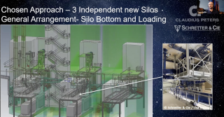
14 July 2022
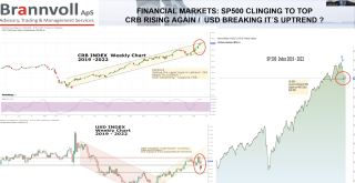
13 July 2022
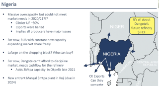
12 July 2022
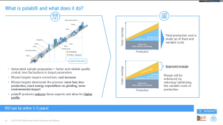
12 July 2022
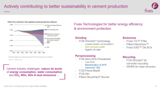
12 July 2022
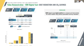
12 July 2022
12 July 2022
12 July 2022
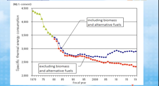
12 July 2022
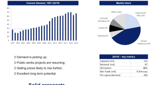
12 July 2022
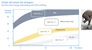
12 July 2022
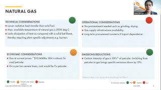
12 July 2022
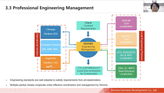
12 July 2022
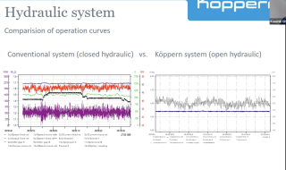
12 July 2022
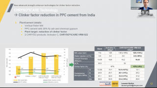
12 July 2022
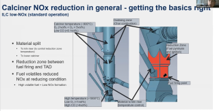
12 July 2022
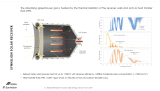
12 July 2022
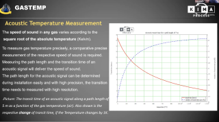
11 July 2022
11 July 2022
11 July 2022
11 July 2022
11 July 2022
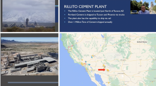
11 July 2022
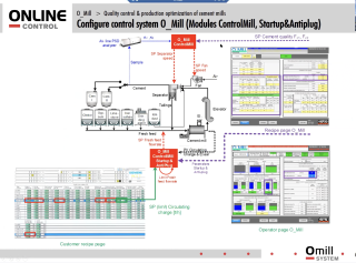
11 July 2022
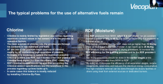
11 July 2022
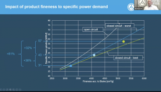
11 July 2022
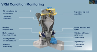
11 July 2022
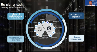
11 July 2022
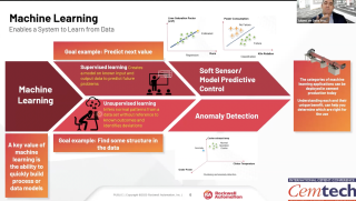
11 July 2022
11 July 2022

11 July 2022
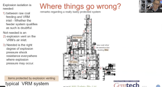
11 July 2022
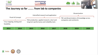
11 July 2022
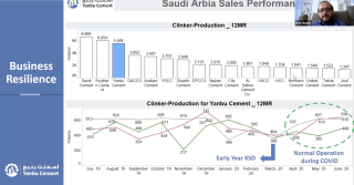
11 July 2022
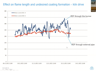
11 July 2022
11 July 2022
11 July 2022
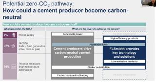
11 July 2022
11 July 2022
11 July 2022
11 July 2022

6 July 2022
1 July 2022
1 July 2022

8 June 2022
12 February 2021
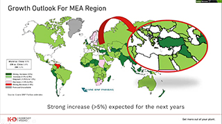
12 February 2021
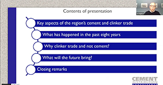
12 February 2021
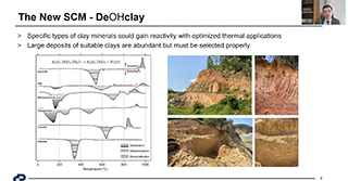
12 February 2021
12 February 2021
12 February 2021
12 February 2021
12 February 2021
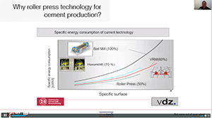
25 September 2020
25 September 2020

25 September 2020
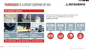
25 September 2020
23 September 2020
22 September 2020
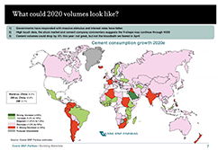
22 September 2020
21 September 2020
20 February 2020
10 February 2020
10 February 2020
10 February 2020
7 February 2020
27 January 2020
23 January 2020
23 January 2020
23 January 2020
23 January 2020
2 May 2019
30 April 2019
18 April 2019
18 April 2019
18 April 2019
12 April 2019
12 April 2019
11 April 2019

10 April 2019
10 April 2019
10 April 2019
9 April 2019
9 April 2019
4 February 2019
17 January 2019
31 July 2018
31 July 2018
31 July 2018
27 July 2018
27 July 2018
27 July 2018
27 July 2018
27 July 2018
27 July 2018
27 July 2018
27 July 2018
27 July 2018
27 July 2018
25 July 2018
25 July 2018
25 July 2018
24 July 2018
24 July 2018
24 July 2018
23 July 2018
23 July 2018
23 July 2018
20 July 2018
20 July 2018
20 July 2018
20 July 2018
20 July 2018
20 July 2018
20 July 2018
20 July 2018
20 July 2018
20 July 2018
20 July 2018
20 July 2018
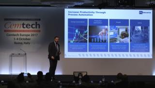
20 July 2018
20 July 2018
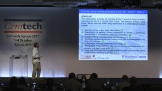
20 July 2018
20 July 2018
20 July 2018
20 July 2018
20 July 2018
19 July 2018
19 July 2018
19 July 2018
19 July 2018
19 July 2018
23 March 2018
23 March 2018
23 March 2018
23 March 2018
23 March 2018
23 March 2018
23 March 2018
23 March 2018
23 March 2018
23 March 2018
23 March 2018
23 March 2018
23 March 2018
23 March 2018
23 March 2018
22 March 2018
26 October 2017
26 October 2017
26 October 2017
26 October 2017
14 August 2017
14 August 2017
14 August 2017
14 August 2017
14 August 2017
14 August 2017
14 August 2017
14 August 2017
14 August 2017
14 August 2017
14 August 2017
14 August 2017
14 August 2017
14 August 2017
18 July 2017
18 July 2017
18 July 2017
16 June 2017
16 June 2017
16 June 2017
16 June 2017
16 June 2017
14 February 2017
14 February 2017
14 February 2017
14 February 2017
14 February 2017
14 February 2017
14 February 2017
14 February 2017
14 February 2017
14 February 2017
13 February 2017
13 February 2017
13 February 2017
19 January 2017
19 January 2017
17 January 2017
17 January 2017
17 January 2017
6 January 2017
18 August 2016
18 August 2016
18 August 2016
18 August 2016
17 August 2016
17 August 2016
17 August 2016
16 August 2016
16 August 2016
16 August 2016
12 August 2016
12 August 2016
12 August 2016
11 August 2016
11 August 2016
11 August 2016
10 August 2016
10 August 2016
10 August 2016
8 August 2016
8 August 2016
8 August 2016
6 May 2016
6 May 2016
6 May 2016
6 May 2016
6 May 2016
6 May 2016
6 May 2016
6 May 2016
6 May 2016
6 May 2016
6 May 2016
6 May 2016
6 May 2016
6 May 2016
6 May 2016
6 May 2016
6 May 2016
6 May 2016
6 May 2016
6 May 2016
6 May 2016
25 April 2016
25 April 2016
11 March 2016
11 March 2016
11 March 2016
11 March 2016
11 March 2016
11 March 2016
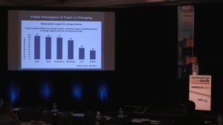
11 March 2016
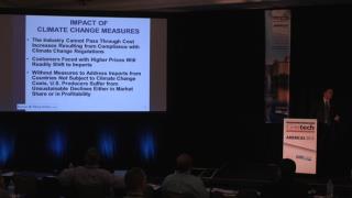
11 March 2016
11 March 2016
11 March 2016
11 March 2016
11 March 2016
11 March 2016
11 March 2016
11 March 2016
11 March 2016
11 March 2016
11 March 2016
11 March 2016
11 March 2016
21 December 2015
15 December 2015
15 December 2015
15 December 2015
15 December 2015

15 December 2015
15 December 2015
15 December 2015
15 December 2015
15 December 2015
15 December 2015
15 December 2015
15 December 2015
2 December 2015
2 December 2015
2 December 2015
2 December 2015
2 December 2015
2 December 2015
2 December 2015
2 December 2015
2 December 2015
2 December 2015
2 December 2015
2 December 2015
21 August 2015
21 August 2015
21 August 2015
21 August 2015
21 August 2015
21 August 2015
21 August 2015
21 August 2015
21 August 2015
21 August 2015
21 August 2015
21 August 2015
21 August 2015
21 August 2015
21 August 2015
21 August 2015
21 August 2015
21 August 2015
21 August 2015

21 August 2015
20 August 2015
20 August 2015
18 August 2015
18 August 2015
18 August 2015
18 August 2015

30 June 2015
29 June 2015
29 June 2015
29 June 2015
29 June 2015
29 June 2015
29 June 2015
29 June 2015
29 June 2015
29 June 2015
29 June 2015
4 June 2015
4 June 2015
2 June 2015
2 June 2015
2 June 2015
2 June 2015
29 May 2015
29 May 2015
28 May 2015
28 May 2015
28 May 2015
18 February 2015
17 February 2015
13 February 2015
13 February 2015
Try searching for another title.